Summer 2020:
Develop stud plan based on your groups wall assembly components. Complete one thorough plan of this type. You will need to complete the projects stud plans for the final submission.
Considerations:
confirm your foundation wall location
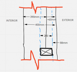
the sketch exterior wall is approximately 390mm. starting from the inside face edit your plan wall match your exterior wall assembly group.
Example:
- group 1 wall assembly is 450 mm thick, extend the wall to match 450 mm
- locate exterior edge of stud distance from exterior finish (88 mm in this example)
- that would be the line of your concrete slab edge or foundation wall
- the Interior edge will be at 200 mm
- align your studs at the exterior face of your 200mm concrete foundation wall
- start with one layout point for your 600 mm oc (on center)
- at windows indicate your studs are cripples by hatching them and using a light dashed line.
- utilize your ground-floor as a base drawing (consider XREF thing your plan into your stud plan)
Reference assignment from previous semester:
Develop Stud plan details based on your groups wall assembly components. Complete one thorough plan of this type. You may complete additional stud plans for extra credit.
Considerations:
align your studs at the exterior face of your 8 inch concrete foundation wall
start with one layout point for your 16” oc (on center)
at windows indicate your studs are cripples by hatching them and using a light line weight
utilize your ground-floor as a base drawing (or above)
Lecture notes:
https://openlab.citytech.cuny.edu/bt2resources/files/2020/03/16-Stud-layouts-2020S_PDF.pdf
Drawing naming chart:
| DRAWING LIST, AS OF ASSIGNMENT B05 | ||
| SHEET NUMBER | SHEET NAME | DESCRIPTION, CONTENT NOTES |
| STRUCTURAL SHEETS | ||
| S-010 | FOOTING PLAN | GRIDS, GRID DIMENSIONS, COLUMN TAGS, FOOTING STRUCTURAL CALCULATIONS |
| S-101 | FIRST (GROUND) FLOOR FRAMING PLAN | JOISTS, RIM JOIST, ANNOTATION (JOIST TYPES AND SIZES) SPANNING DIMENSIONS |
| S-102 | FIRST (GROUND) FLOOR JOIST PLAN | STUDS (CRIPPLES, KING, TRIMMER) INTERIOR AND EXTERIOR, ANNOTATION |
| ARCHITECTURAL DRAWINGS | ||
| A-100 | CELLAR PLAN | WINDOWS, ARCHITECTURAL CASEWORK, LABELS, DOORS… |
| A-101 | GROUND FLOOR | (guest rooms) INTERIOR WALLS, BATHROOM FIXTURES, ARCHITECTURAL CASEWORK, LABELS, DOORS… |
| A-102 | FIRST FLOOR | (living room kitchen) INTERIOR WALLS, BATHROOM FIXTURES, ARCHITECTURAL CASEWORK, LABELS, DOORS… |
| A-103 | SECOND FLOOR | (mezzanine bedroom) INTERIOR WALLS, BATHROOM FIXTURES, ARCHITECTURAL CASEWORK, LABELS, DOORS… |
| A-104 | ROOF PLAN | INTERIOR WALLS, BATHROOM FIXTURES, ARCHITECTURAL CASEWORK, LABELS, DOORS… |
| A-201 | ELEVATIONS EAST & SOUTH | ELEVATION MARKERS, HEAVY GROUND CUT LINE, ELEVATION MARKS [OPTIONAL] CELLAR OUTLINE |
| A-202 | ELEVATIONS NORTH & WEST | ELEVATION MARKERS, HEAVY GROUND CUT LINE, ELEVATION MARKS [OPTIONAL] CELLAR OUTLINE |
| A-301 | BUILDING SECTIONS | [OPTIONAL] OVERALL SECTION(S) |
| A-510 | [OPTIONAL] PLAN WALL DETAILS | CORNERS, DOOR AND WINDOW JAMB |
| XREF AUTOCAD DRAWINGS (LINKED DWG FILES) | ||
| N/A | GRID | (optional on this type project) GRIDS, GRID DIMENSIONS, NORTH ARROW |
| N/A | TITLE BLOCK | PROJECT, STUDENT, CLASS, AND DRAWING INFORMATION, YOUR LOGO |
This is a tentative value and will shift as you develop your project.


