ENT 4410 Problem 4

For Problem 4, me and Nesreen had to come up with a solution to construct and plan the scenery for “Mary Martin”. Most of the scenery is being constructed by John Creech Design and Production Incorporate. Compared to the previous two projects, this definitely gives us less stress for the drafting phase. For the problems itself;

1. We had to figure out how the suitcase is going to be carried on stage.

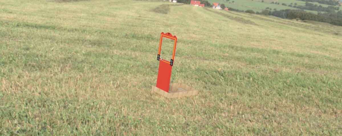
2. How one of the picture frames are going to be projected on stage.

For the suitcase, my idea was to create a prototype test to figure out the proper fold.

Prototype Test Piece

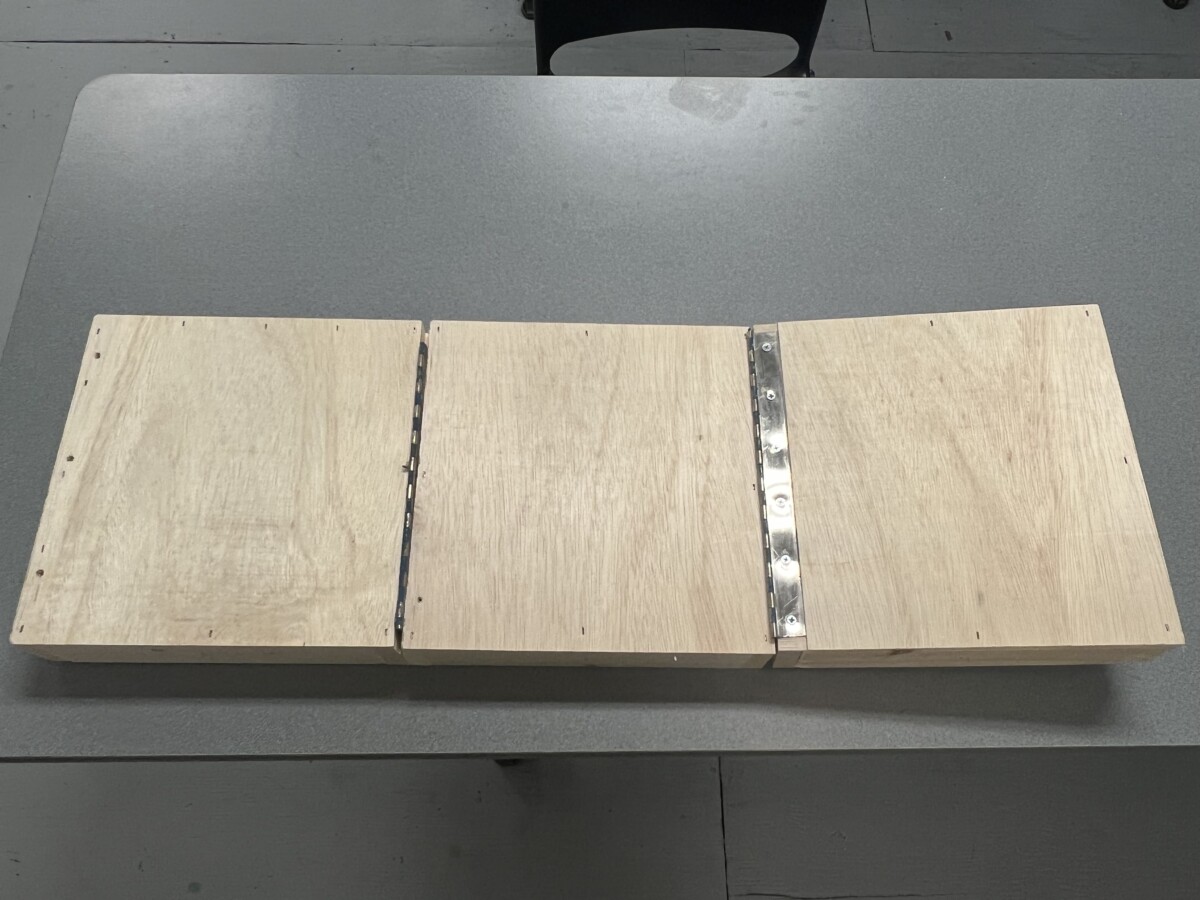
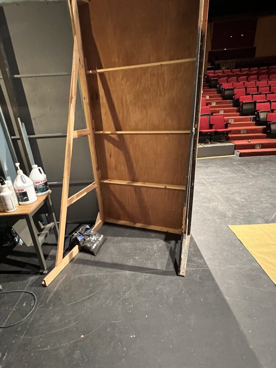
What I decided to do in this test piece was to utilize piano hinges for the flats to fold into itself. For the flats itself, I took some scrap lumber from the scene shop (1×3 Ply) and created small squared flats. Once I stapled in all the framing members, I also applied lauan face cover to represent the suitcase’s exterior. In this test piece, I decided to do two different placements for the installing of the piano hinges. One flat would have the hinge on top and the other to the side. The flat to the left would have the piano hinge connected to the side to the one in the middle. The process of installing the piano hinges involves in scraping off material with a router. To take some of the material off from the flats, I used a 3/16″ drillbit and applied a fence with a stopper for the flats to be run on. After scraping the flats, I took the piano hinges, measured the holes onto the flat and drilled some holes for mechanical flat head screws to be placed. The reason why you want flathead screws to be placed on the piano hinge is for maximum rotation. The flat itself would also be blocked from the other to prevent the proper close. Turns out, the first example of the left of the picture is the most effective way to properly fold a flat inwards. The other example on the right isn’t the most proper because it doesn’t close all the way. For that reason, keeping the hinges inwards helps seal the flats to fold in itself.

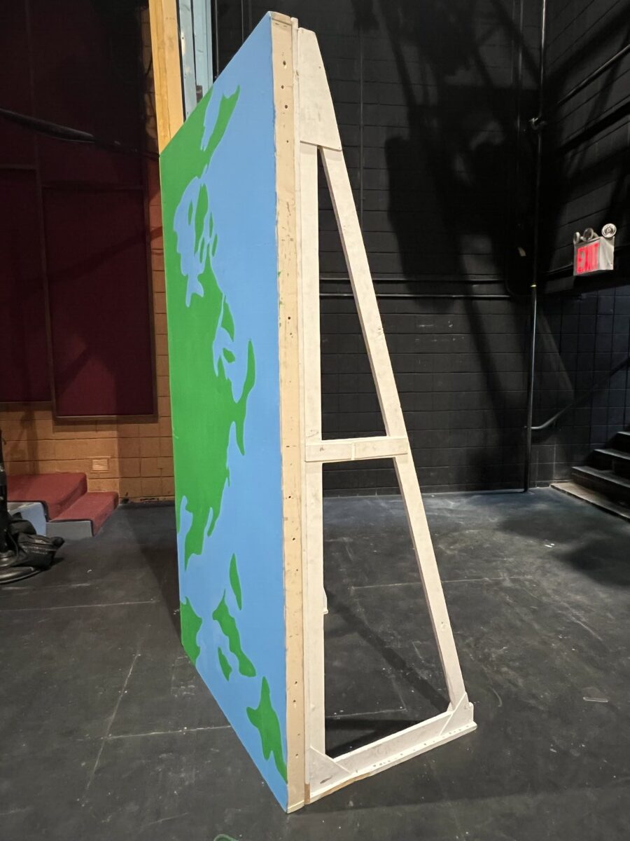
On the construction drawing for the suitcase, one of the most difficult problems was finding out how to keep the kissing booth standstill after transforming. Despite not showing this on the ePortfolio, one way to allow this to work is to use footers to keep the kissing booth in tact. For the detail itself, you really want the suitcase to be light as possible. I tried to make the suitcase as realistic as possible by drafting it in Fusion 360. The baseboard for the suitcase is made up of 1×3 ply with lauan facecover. The stand itself is also made out of the same material as the baseboard. The difference is that the stand will be painted with Regal Select Interior Paint mixed with flameproof adhesive. For the top part aka the Kissing Booth, there’s a whole lot of detail to be defined. For the speakers itself, the material would be made out of baseboard. With the diaphragms, the material would be also the same. But to get the circular shape, using a jigsaw with a circular jig would help recreate it. Once the shape is created, using narrow crown staples and glue would help reinforce it. In the center of the framing, it mimics as an LED strobe light. For the material, I would use PVC foam to put in the center. The suitcase would also have locking hinges to lock it in place. After listing all the materials, the suitcase should be light enough to carry.

Test Piece on Fusion 360

For the second part of the problem is dealing with the projector being rolled on stage. For this to happen especially if handling a load-in/load-out, using cart smart casters with core wheels and a locking mechanism is ideal for this job. One important tip is to make sure there’s enough room for the casters to sit on when attaching it to the framing of the projector. Materials included should be 1″ Philips Steel Flat Head Screws, 3/16 hex bolts and 1/2″ fasteners. Another thing is to make sure the casters are swivel to prevent constrained movement in a linear direction. You want as much free movement as possible when pushing the platforms onto the stage. To keep the platform in place is using a stop block. The material of the casters is depended on the material of the stage floor. If the stage floor is made out of concrete, a good recommendation is steel wheels because of less abrasion and pressure. In this case, were using core wheels because the stage floor is not made out of concrete and instead made out of a softer material like black sprung wood covered layered with marley.

ENT 4410 Technical Direction

For Problem #3, me and Charles objective was to plan the construction for an upcoming show. For this show, there will be a complete set design involving a vast number of flats that are 12′ long and does require crown based molding. For the molding process, me and Charles decided to do a test piece with MDO to mimic the possibility of attaching it to a flat. This serves the purpose as a piece of crown molding. The problem is trying to figure out how to bend the MDO to create a circular shape like a curved flat. I decided to do some kerf bending. To do this, we decided to make 5/16″ cuts with the table saw and use a cross cutting jig. I also made 1″ increments to make each cut on the MDO. Once the cutting has been finished. I used a round circular like piece to paste it on the MDO. To do this, I mixed in glue and some sawdust and brushed in on the cut lines to fill in the gaps. Once that’s settled, we basically proved that you bend crown molding to use for a curved flat. The next issue with this project is trying to figure out how to prevent the flats from shaking especially the door framed flat. To do this, me and Charles agreed to do some rigging. We took a 6′ schedule 40 pipe and decided to figure out the total load by using a 1/3 yield. Because the flat was about 4′ in length, we decided to make the span around 2′. The point load turned out to be around 600 lbs which is well over the WLL we need to rig the flat. Once figured out the load, we then grabbed the necessary rigging equipment in the scene shop. This includes, 1/4″ galvanized aircraft cable, 1/4″ shackles and thimbles, some jaw to jaw turnbuckles, d-rings. To set up the rigging hardware to the flat, we measured/cut the wire rope to about 8′-6″. We then had to drill the flat to make insertion points for the loop end cable. To do that, we took one end of the GAC cable, a nicopress sleeve and thimble and made a loop by using a swage tool. After doing that, we inserted the wire rope all the way until it reached the bottom of the flat. Then we had to insert a d-ring on the bottom of the flat by putting in some lag screws. We then took the d-ring and tightened it 5/16″ hex nuts and fasteners. Once that’s settled, we made another loop and hooked it on to the d-ring with a shackle. Me and Charles then stood up the flat and drilled it from the floor to stabilize it. Once that’s finished, we put some steel chain, looped it to the pipe, added a shackle and turnbuckle and connected the loop end to it. After finishing that, I levered the chain hoist and raised the pipe until there was complete tension from the wire rope to the flat. Rudy and Jorge helped volunteered to shake both the 4×8 and door frame flat we did later. The first test shows Rudy shaking the 4×8 flat. On the 2nd and 3rd test piece, Jorge shakes the door frame flat. One without jacks and one with them. Turns out, a lot of the shaking was mitigated due to the tension. For the show, we would install a pipe with a chain hoist system in the theatre to create pick points directly on the top of the flats when doing so for the show. The flats itself would also be jacked to prevent the shaking from really happening.

Test #1 with 4×8 Flat

https://www.youtube.com/watch?v=OBK4LvQlmlo

Test #2 with Custom Door Frame Flat

Test #3 with Custom Door Frame Flat with Jacks

Construction Drawings – Test Pieces & Set Design

ENT 4410 Technical Direction

Problem #2: For the next assignment, our task was to be in charge for the scenic crew in an upcoming show. Like the previous assignment, we had three groups working as technical directors for the show. The details of the assignment include a large deck with a floor elevation from 3′ to 6′-4″. The deck is built for two shows 8 days after the Haunted Hotel. The first event is a band concert while the other is a talent show. The band members wants the floor to be painted based on their main logo. The talent show on the other hand also wants a painted deck in black. Other components include two staircases for the deck. For the project itself, me and Colin were responsible for many things. 1. Create a working schedule for the scenic crew/build. 2. Figure out how to deal with the construction and painting of the deck. 3. Dealing with the construction and painting of the staircases. 4. Drafting and assembling the deck and staircases. The main glaring issue with this project was time management. We only had about 10 days to get a huge amount of work done. Another problem was the handling of the schedules. Because the scenic strike for the Haunted Hotel was happening on a Monday/Tuesday, the only possible time the scenic crew could work for our show is 2:30 to 6. Another thing was figuring out the paint surface layer for the deck. The issue is that there’s two shows happening back to back. To deal with this, we decided to add masonite and vinyl over the deck. Once the first show ends, the stage crew will then install high gloss marley for the next show. For the staircases, the front has a rise of 9″ while the back has 8″. One important rule is to make sure the total for the rise and run equals 17 to 18″. The run for both staircases are going to be 8″. Another problem is the tripping hazard for the back staircase. To mitigate this issue, an 8″ tripping hazard is installed.

ENT 4410 Technical Direction

Assignment 1: PB&J Sandwich

For our first assignment, we were given specific instructions on making a peanut butter and jelly sandwich. For this project, the entire classroom was divided into three groups. To do this, we needed to create construction drawings of the sandwich, a budget, and materials that can either be purchased or rented in the shop. Once the requirements are met, any materials that are needed for the PB&J are loaded in to a box for delivery. Other deliverables include an instructions sheet, a receipt and video instructions with a QR code. In terms of the results, while the volunteer did make a peanut butter and jelly sandwich the proper way, one of the materials were excessively used which was the paper towels. If we redid the project beforehand, clarifying the instructions sheet would be the main priority. This would change the results on the creation of the PB&J Sandwich.

Receipt for Materials
Top and Side View of PB&J Sandwich
Budget Spreadsheet
P&J Instructions
Video Instructions

Culmination Project

culmination-proposal tristen

ENT 4499 – Culmination Presentation

Poster for Culmination:

IMG_E1114


Budget for Culmination:

Floor Canvas – 144” Canvas NFR 9 Yds – $228.00

Paint for Flats: $158.02

Paint for Floor Canvas: $214.99

Total: $601.01

Calendar:


Culmination Meetings with Technical Advisor ENT4499

Groundplan Set Design for Culmination

Section View for Theatre Culmination

Scenic Set Design For City Tech Around the World Rough Draft

Paint  Elevations  for  Floor  Canvas  &  Flats  


Paint Elevations for Floor Canvas Finalized

Flat 1 Fully Painted Without Added Paint Layer 

Flat 2 Fully Painted Without Paint Layer 

Flat 1 With Paint Layer 

Flat 2 With Paint Layer 

Floor Canvas Painted with Regal Select 

Both Flats Jacked and weighted with Sandbags

Complete Set Design. This includes 2 6′ Drapes hung. NFR Floor Canvas and two 4×8 Flats.