Connecting a Circuit
On a breadboard there are many tiny holes. Each hole will hold a wire or component lead. The board is divided into four sections; two sets of two rows and two sets of five rows. The five rows in each vertical group are connected together (top to bottom), while each horizontal group at both ends is connected together (side by side) as shown in Figure 1.
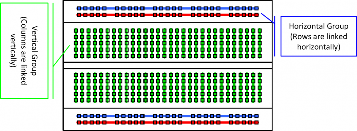
Figure 1 Sections in a breadboard
There are two color Lines that represent the two sets of two rows at opposite ends of the board (as shown in Figure 1). The Blue lines are for the GND (-) connection and the Red lines are for the Voltage (+) connection. Rows A-E represent the first section of five rows, while rows F-G represent the second section (These rows are not connected together horizontally).The numbers on the board represent the columns. Each end of the components that are being connected together must be placed in the same.
When inserting components, bend both ends of the protruding wire on the component and gently push then into the hole. The components can be placed either in the same row (e.g., 10b and 15b) or in different columns, with each end across the groove in the center of the board (e.g., 5c and 5g) as shown in Figure 2.
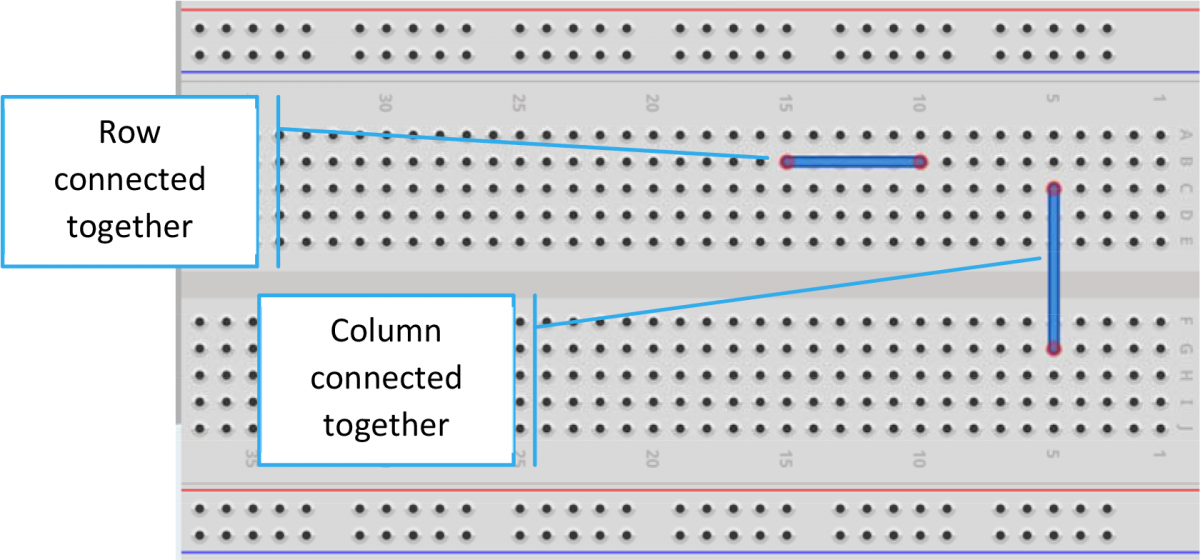 Figure 2 Connecting row and columns
One of the ways you can place components on the breadboard is in series. Figure 3 is an example of how to place components in series.
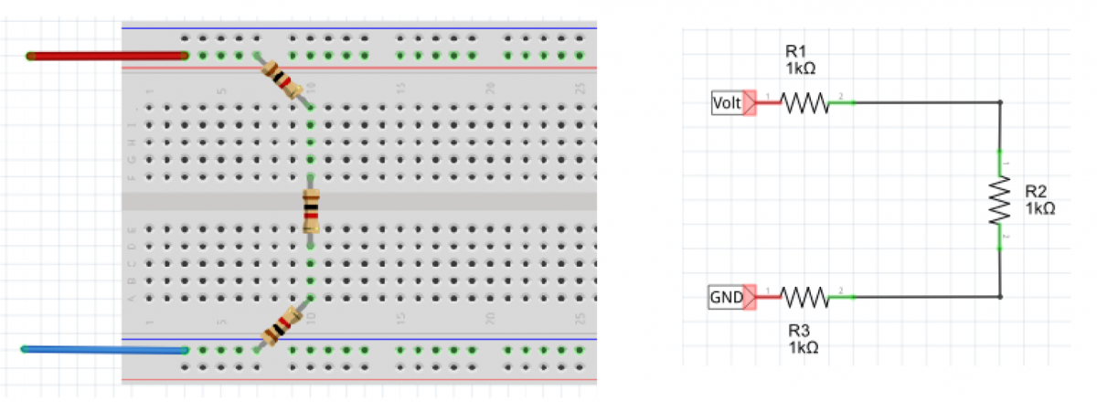
Figure 3 Connecting components in series
Components can be also connected in parallel. Here in Figure 4, two resistors are connected in parallel.
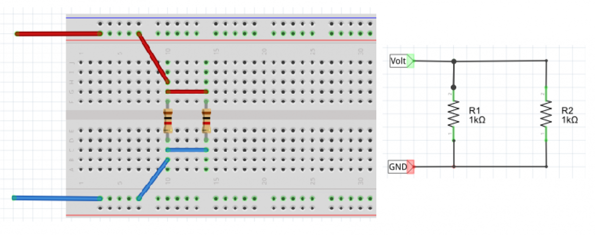
Figure 4 Connecting components in parallel
Test yourself
- Understanding a breadboard
- Troubleshooting three resistors is series
- Calculating a total resistance in parallel
- Calculating in series-parallel circuit
Tags:
Systems,
Breadth of knowledge
Operational Instruction (Click here!)
How to use the power supply -> Watch the video
Tags:
Inquiry/Analysis,
Breadth of knowledge,
Systems
OPERATION
Before taking any measurements, read the Safely Information Section. Always examine the instrument for damage, contamination (excessive dirt, grease, etc.) and defects. Examine the test leads for cracked or frayed insulation. If any abnormal conditions exist do not attempt to make any measurements.
Max. Hold Feature
Press ”MAX” to toggle in and out of the Maximum Hold mode. (Holding the highest reading.) In the MAX mode, the MAX annunciator is displayed and maximum reading arc stored in display register, if the new reading is higher than the reading being displayed, the higher reading is transferred to the display register. A “higher” reading is defined as the reading with the higher absolute value.
The MAX hold function is disable in the frequency count mode, but the MAX annunciator is still displayed.
Voltage Measurements
- Connect the red test lead to the “VΩ” jack and the black test lead lo the “COM” jack.
- Set the Function/Range switch to the desired voltage range and press the ”AC/DC” switch to toggle between the desired voltage type. If magnitude of voltage is not known, set switch to the highest range and reduce until a satisfactory reading is obtained.
- Connect the test leads to the device or circuit being measured.
- For dc, a (-) sign is displayed for negative polarity; positive polarity is implied.
Current Measurements
- Set the Function/Range switch to the desired current range and press the “AC/DC” switch toggle between to the desired current type.
- For current measurements less than 200mA, connect the red test lead lo the “mA” jack and the black test lead to the “COM” jack.
- For current measurements over 200mA or greater, connect the red test lead to the “10A” jack and the black test lead to the “COM” jack.
- Remove power from the circuit under test and open the normal circuit path where the measurement is to be taken. Connect the meter in series with the circuit.
- Use caution when measuring 10 amps on 10A range for 60s, please waiting for 10 minutes for next measurement of 10 amps for safety reason.
Resistance and Continuity Measurements
- Set the Function/Range switch to the desired resistance I. Set the Function/Range switch to the desired resistance
- Remove power from the equipment under test.
- Connect the red test lead to the “VΩ” jack and the black test lead to the “COM” jack.
- Touch the probes to the test points. In ohms, the value indicated in the display is the measured value of resistance. In continuity test, the beeper sounds continuously, if the resistance is less than 40Ω±20Ω.
- When using 2000MΩ range; the 2000MΩ range has a fixed 10±1-count offset in the reading. When the test leads are shorted together in the ranges, the meter will display 010. The residual reading must be subtracted from the reading obtained in step 4 when this range is used. For example, when measuring 1100MΩ on the 2000MΩ range, the display will read 1110, from which the 10 residual is subtracted to obtain the actual resistance of 1100MΩ.
WARNING
The accuracy of the functions might be slightly affected, when exposed to a radiated electromagnetic field environment, eg, radio, telephone or similar.
Diode Tests
- Connect the red test lead to the “VΩ” jack and the black lest lead to the “COM” jack.
- Set the Function/Range switch to the “→I-” position.
- Turn off power to the circuit under test.
- Touch probes to the diode. A forward-voltage drop is about 0.6V (typical for a silicon diode).
- Reverse probes. If the diode is good, “OL” is displayed. If the diode is shorted, “.000″ or another number is displayed.
- If the diode is open, “OL” is displayed in both directions.
- If the junction is measured in a circuit and a low reading is obtained with both lead connections, the junction may be shunted by a resistance of less than I kΩ. In this case the diode must be disconnected from the circuit for accurate testing.
Capacitance & Inductance Measurements
- Set the Function/Range switch to the desired F (capacitance) or H (inductance) range.
- Never apply an external voltage to the Cx Lx sockets. Damage to the meter may result.
- Insert the capacitor or inductor leads directly into the Cx Lx socket.
- Read the capacitance or inductor directly from the display.
Transistor Gain Measurements
- Set the Function/Range switch to the desired hFE range (PNP or NPN type transistor).
- Never apply an external voltage to the hFE sockets. Damage to the meter may result.
- Plug the transistor directly into the hFE socket. The sockets are labeled E, B and C for emitter, base and collector.
- Read the transistor hFE (dc gain) directly from the display.
Frequency Measurements
- Set the Function/Range switch to the Hz position.
- Connect the red test lead to the “VΩ” jack and the black test lead to the ”COM” jack.
- Connect the test leads to the point of measurement and read the frequency from the display.
Duty Cycle Measurements
- Set the Function/Range switch to the DUTY% position.
- Connect the red test lead to the ”VΩ” jack and the black test lead to the “COM” jack.
- Connect the test leads to the point of measurement. The display will indicate 10% to 90.0% of the frequency duly cycle.
Tags:
Inquiry/Analysis,
Breadth of knowledge,
Systems
DMM (Digital Multi-meter, R.S.R. 1007):
A test tool used to measure two or more electrical values, principally voltage (volts), current (amps) and resistance (ohms). It is a standard diagnostic tool for technicians in the electrical/electronic industries.
Equipment that supplies a constant DC voltage to its load.
Oscilloscope (GW INSTEK GDS-1102A-U):
a type of electronic test instrument that allows observation of constantly varying signal voltages, usually as a two-dimensional plot of one or more signals as a function of time. Other signals (such as sound or vibration) can be converted to voltages and displayed.
Tags:
Inquiry/Analysis,
Breadth of knowledge,
Systems