Contents
Equipment/Parts Needed
- PC (Altera Quartus II V9.1 installed)
- DE-2 board
Objective
- To investigate the behavior of a D flip flop with the Altera Quartus II program. A simulation waveform will be constructed and used to exercise the inputs and observe the resulting output.
- To show how flip flops can be used as frequency dividers/counters. The DE-2 board will be programmed with JK flip flops configured as a frequency divider/counter.
Discussion
- This experiment will cover the operation of the two types of edge triggered flip flops: D and JK.
- Flip flops are different from combinational logic in that their output depends on past and present input states.
- Flip flops have synchronous inputs that are sampled on the positive or negative going edge of the clock input.
- They also have asynchronous inputs that are level sensitive and independent of the clock input. Asynchronous inputs override synchronous inputs when there is a conflict.
- Using Quartus II adder circuits will be constructed using the Graphic Editor. The circuit will then be tested and its operation verified on the DE-2 board.
Part 1: Construction and Simulation of a D Flip Flop Circuit
- Start the Quartus II software. Select File – New Project Wizard. And create a new project name under the directory C:\altera\91sp2\quartus\your last name \Lab11. Assign the project name Lab11_1, assign Cyclone II for the device family, and select the EP2C35F672C6 chip in the Family & device settings.
- Open a New Block Diagram/Schematic file and draw the circuit for the D flip flop.
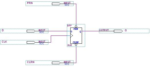
Figure 11-1 D Flip-Flop
-
- After a successful compilation, open a new Vector Waveform file and construct the input waveforms: CLK, PRN, CLRN and D. Set the following parameters in the Simulation waveforms: Grid Size=100ns; End Time=1µs.
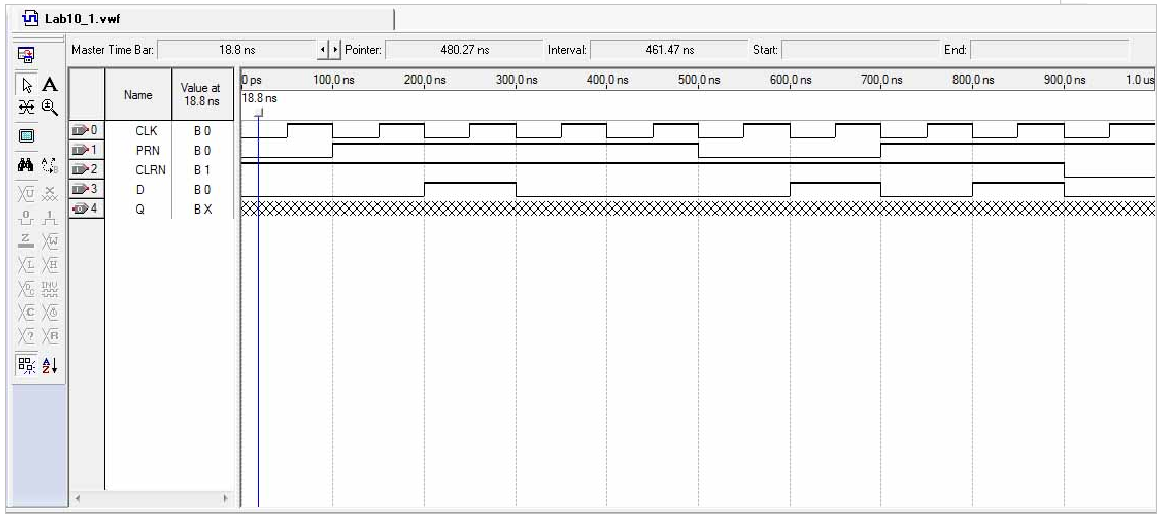
- The CLK period should be set to 100ns. After a successful simulation which creates the output Q waveform, print out a copy of your schematic diagram and simulation waveform.
Part 2: Construction of a 5 stage JK Flip Flop Frequency Divider/Counter Circuit
1) Create a new project name Lab11_2. Select File – New Project Wizard to open a New Block Diagram/Schematic file.2) Construct the frequency divider circuit using five JK flip flops below.
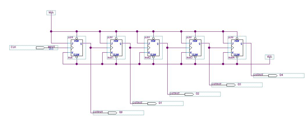
Figure 11-2 Frequency Divider/Counter Circuits using JK Flip Flops.
Figure 11-2 Frequency Divider/Counter Circuits using JK Flip Flops.
3) After a successful compilation, open a new Vector Waveform file and construct the input waveforms: CLK. Set the following parameters in the Simulation waveforms: Grid Size=100ns; End Time=2µs. The CLK period should be set to 100ns.
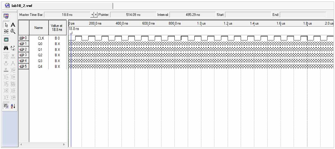
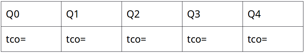
4) After a successful simulation, choose the Timing Analyzer Tool from the Processing menu. Record the propagation delay (found in the tco tab) at the Q output with respect to the clock input:
5) Now you are ready to assign Pin Names and Numbers as shown in the following Table.

6) Save and compile the design again before programming. Then connect DE-2 board to computer. (If you’re not sure, refer to the Part 2 of Lab 7 manual.)
Questions/Report
- A JK flip flop can be made to operate as a D flip flop by adding an external Inverter gate and making the appropriate connections. Draw the schematic for this circuit.
- A D flip flop can be made to operate in a toggle mode (divide its CLOCK input frequency by two) by adding an external Inverter gate and making the appropriate connections. Draw the schematic for this circuit.
- Circuitry in a digital clock takes the output of a 65,536 Hz Oscillator and divides it down to 1 Hz (1 pulse per second). How many flip flops are needed to do this?
- Write in the states (Reset, Set, Asynch. Reset, Asynch. Set) on the output waveforms of the D flip flop from Part 1.

