Connecting a Circuit
On a breadboard there are many tiny holes. Each hole will hold a wire or component lead. The board is divided into four sections; two sets of two rows and two sets of five rows. The five rows in each vertical group are connected together (top to bottom), while each horizontal group at both ends is connected together (side by side) as shown in Figure 1.
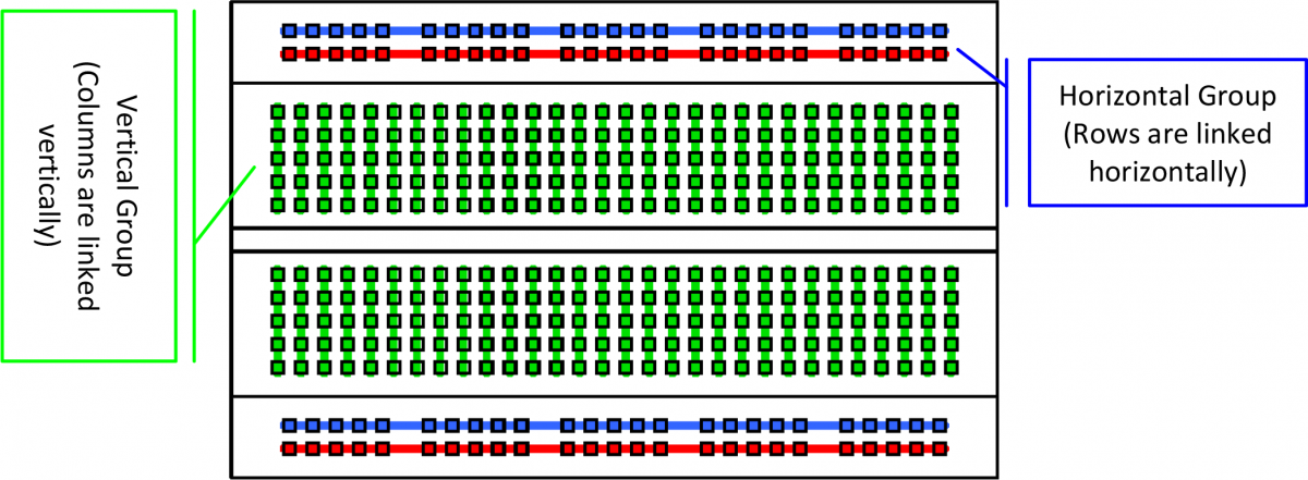
Figure 1 Sections in a breadboard
There are two color Lines that represent the two sets of two rows at opposite ends of the board (as shown in Figure 1). The Blue lines are for the GND (-) connection and the Red lines are for the Voltage (+) connection. Rows A-E represent the first section of five rows, while rows F-G represent the second section (These rows are not connected together horizontally).The numbers on the board represent the columns. Each end of the components that are being connected together must be placed in the same.
When inserting components, bend both ends of the protruding wire on the component and gently push then into the hole. The components can be placed either in the same row (e.g., 10b and 15b) or in different columns, with each end across the groove in the center of the board (e.g., 5c and 5g) as shown in Figure 2.
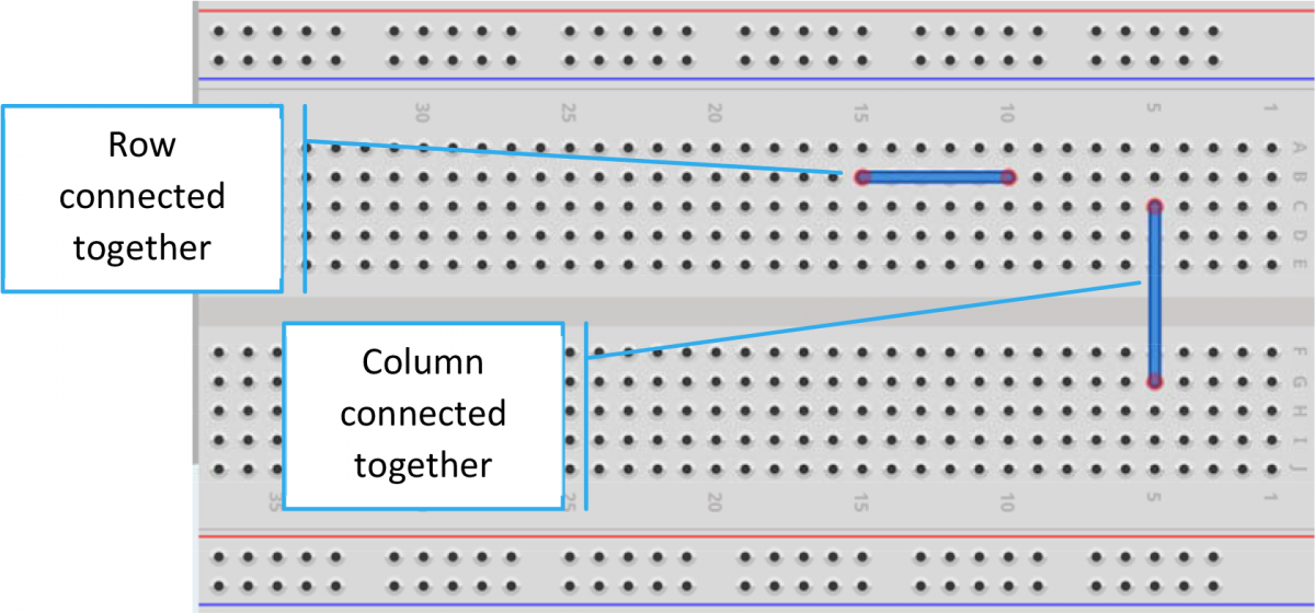 Figure 2 Connecting row and columns
One of the ways you can place components on the breadboard is in series. Figure 3 is an example of how to place components in series.
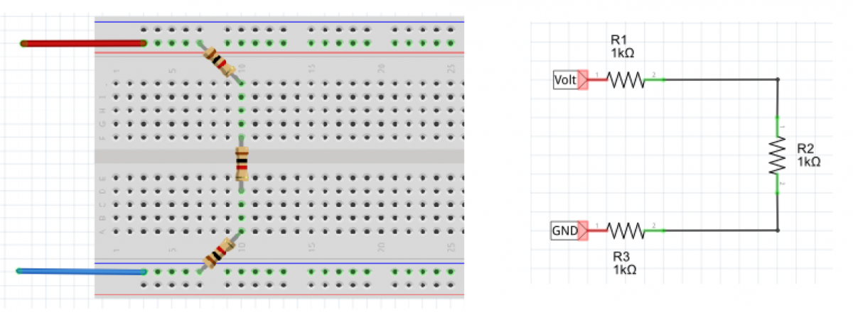
Figure 3 Connecting components in series
Components can be also connected in parallel. Here in Figure 4, two resistors are connected in parallel.
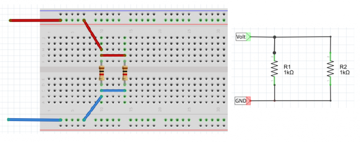
Figure 4 Connecting components in parallel
Test yourself
- Understanding a breadboard
- Troubleshooting three resistors is series
- Calculating a total resistance in parallel
- Calculating in series-parallel circuit
Tags: Breadth of knowledge, Systems

