Contents
Equipment/Parts Needed
- 5V DC Power Supply
- Logic Probe (from the Digital Trainer)
- Oscilloscope
- Function Generator
- EMT 1250L Parts Kit
Objective
- To become familiar with constructing a circuit from a schematic diagram.
- To use the Oscilloscope to measure the parameters of Periodic waveforms..
Discussion
- The DIP Toggle switch will be used to connect +5V and GND to a LED and Resistor network.
- The Function Generator will be set to various settings and then measured on the Oscilloscope.
Part 1: Schematic Diagram
- Construct the circuit shown below and verify that each LED is controlled by each of the Toggle switches.
- The LED Cathode is the lead closest to the flat edge of the LED package.
- Use the Logic Probe to debug the circuit and measure the voltages as shown below.
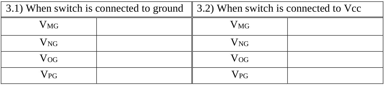
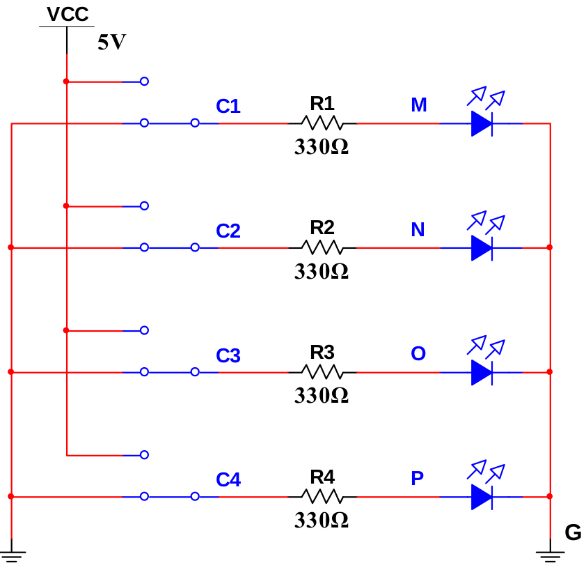
Figure: 1-1 Circuit with the switch connected +5V or Ground
Part 2: Periodic Waveform Parameters
Connect the OUTPUT of the Function Generator to the Oscilloscope. Set the Function Generator as shown and make measurements with the Oscilloscope using the T1 T2 and V1 V2 cursors.
1. Frequency = 1 kHz, Amplitude = 2VPP, Offset = 2V, Duty Cycle = 50%
Oscilloscope Measurements
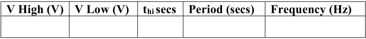
2. Frequency = 10 kHz, Amplitude = 2.5VPP, Offset = 2.5V, Duty Cycle = 20%
Oscilloscope Measurements
3. Frequency = 20 kHz, Amplitude = 2VPP, Offset = 2V, Duty Cycle = 80%
Oscilloscope Measurements
Questions/Report
- Compare using a Logic probe VS an Oscilloscope in debugging a circuit. State the advantages of each.
- Calculate the Duty Cycle for the 3 Function Generator settings in Part 2 of the experiment. Use the Oscilloscope readings to calculate Duty Cycle. Do the calculated values agree with the Function Generator settings?

