Overview –
In simplest terms, an electrical circuit is a device that uses electricity to complete a task. These takes may include something complex like turning on a television, or something much more simple like powering a lamp. The circuit is in a closed loop formed by a power source, wires, a fuse, a load, and a switch. Electricity flows through said circuit and is delivered to the object that it is powering, IE: the lamp.
There are three types of circuits which include series, parallel, and series-parallel circuits. Most devices that run on electricity contain an electrical circuit. When the device is connected to a power source, like being plugged into an electrical outlet, electricity can run through the circuit. The excess electricity that is not being used is returned to the original power source which continues the flow of electricity. Any device that consumes the energy flowing through a circuit and converts that energy is called a load. A light bulb is a great example of a load because it consumes the electricity from a circuit and converts it into energy which is heat and light.
A series circuit is the simplest because it only has one possible path for the electrical current to flow. If the electrical current is broken, none of the load devices will work. The difference with parallel circuits is that they contain more than one path for the electricity to flow. So if one path is broken, the other paths will still work. A series-parallel circuit is a combination of the first two. It splits the load between a series circuit and a parallel circuit. If the series circuit breaks, none of the loads will work. If the parallel circuit breaks, the parallel and series circuit will stop working while the other parallel circuits will continue to work.
Ohm’s Law is probably the most well known law that applies to electrical circuits. Ohm’s Law says that an electrical current is directly proportional to its voltage and inversely proportional to its resistance. For example, if voltage increases, the current will also increase. If resistance increases, current decreases. Both situations influence the efficiency of the electrical circuit. To gain a better understanding of Ohm’s Law, it’s important to understand the concepts of current, voltage, and resistance. Current is the flow of an electric charge, voltage is the force that drives the current in a particular direction, and resistance is the opposition of an object to having current pass through it. Ohm’s Law says V = I * R where V is voltage, I is current, and R is resistance. The answer results in Ohms. This formula can be used to analyze voltage, current, and resistance of electrical circuits.
Another important concept in electrical circuits is source voltage. This refers to the amount of voltage that is produced by the power source and applied to the circuit. Source voltage depends on how much electricity a circuit will receive. It is also affected by the amount of resistance within the circuit. Resistance is not affected by voltage or current, but can reduce the amounts of both voltage and current to an electrical circuit.
Sample Problem –
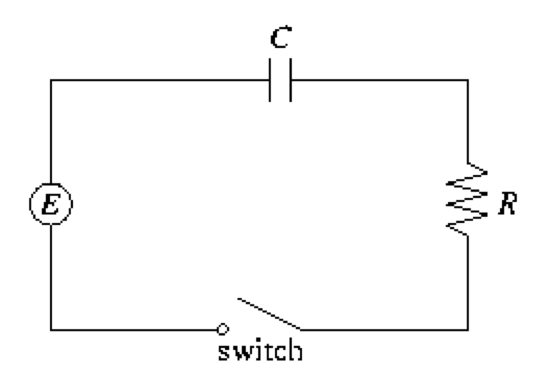
For the circuit above,
R = 20 Ohms
C = 0.05 F
E = 50 V
Initial charge is Q(0) = 0C.
Find the charge and the current at time t.
In order to find the current, we can use Ohm’s law which says I = V/R. Simply plug in and solve.
I = 50V/20 Ohms = 2.5 A
Since we are finding the current at time t, I(t) = 2.5e^(-t)
Similarly, we find the charge:
Q = I * T
Q(t) = 2.5(1 – e^(-t))
Videos –
This video explains basic series and parallel circuits in the form of a cartoon, meant for kids. It’s very simple and easy to follow and demonstrates current flow with the use of a light bulb. The video also shows you how to turn a physical circuit into a schematic or circuit diagram.
This video, which is somewhat lengthy, is more of a PowerPoint presentation than a demonstration. This video goes into some detail of each part of a circuit, how to find measurements of a circuit using Kirchhoff’s and Ohm’s Laws, and even explores more complex circuits such as ones with loops.
Electrical Circuits: The Basics (Creator of video disabled embedding)
This video explains circuits in comparison to a water system, making analogies to how a water system must be closed for water to flow through just as a circuit needs to be closed for current to flow through. The video also introduces some basic tools that are used to measure components in a circuit.

