Date 10/14
Topic: Digital Fabrication 2 (Arduino and other basic components)
Contents
Pre-class
- Introducing the Breadboard
- Go to TinkerCAD learn website and find the Breadboard demonstration page
- Follow the instruction and complete the RGB LED circuit.
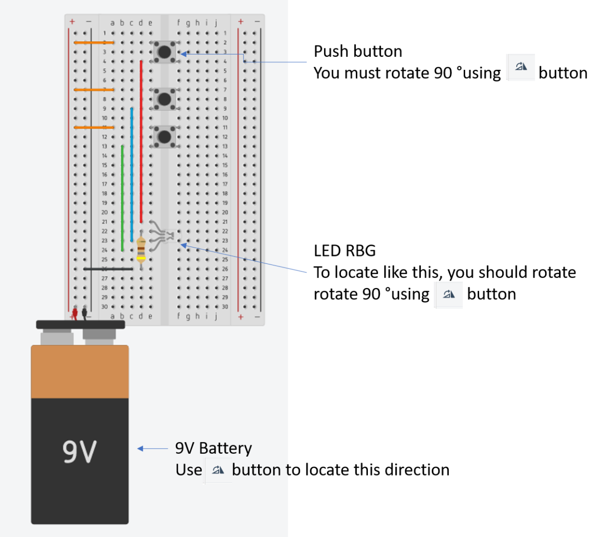
- After completing this circuit, you should see the LED light turned on when you press each of push buttons.
- If something looks wrong, please double check below.
- Make sure that you correctly locate the required components with correct directions.
- The resister used above example was 450 Ω.
- Check you correctly locate the direction of push buttons. (90 º rotated)
- Use the rotation button on the top-left corner to place LED and push button.
- Your pre-class tasks
- Understand how the circuit of breadboard is designed internally.
- Why did you use 450 ohm register?
In-class:
-
-
Ohms’ Law
- UNO Elegoo LED Datasheets.
- In your pre-class module, you used 450 ohms. Why did you use 450 ohms?
- V = I x R
- Battery = 9 v
- Recommended LED current = 0.02A
- Required resister?
- In Arduino circuits
- Arduino I/O voltage = 5 v
- LED recommended current = 0.02A
- Required resister, R = V / I = 5V / 0.02A = 250
-
-
-
Programming with LED
- Build below circuit on TinkerCAD
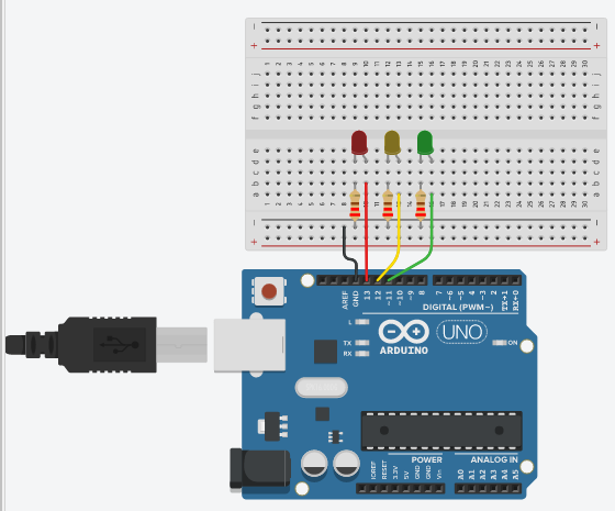
- Use 220 ohms resisters
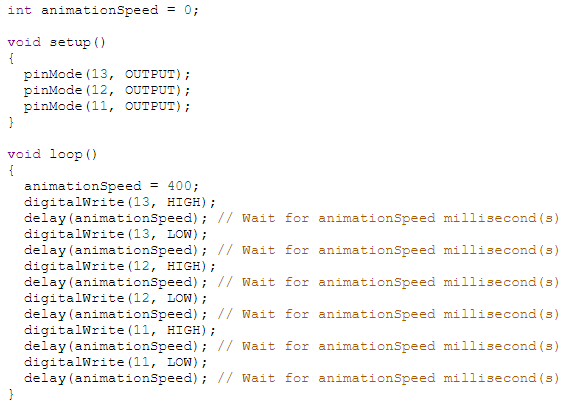
- Write program shown below
- Change the rate of animation to 0.1 seconds
- Change the order of blinking LEDs in Green, Yellow, and RED.
-
-
-
Digital Input
- Build below circuit using your Arduino (NOT on TinkerCAD).

- Required Components
- 220 ohms
- 10k ohms
- LED
- push button
- Program codes shown below
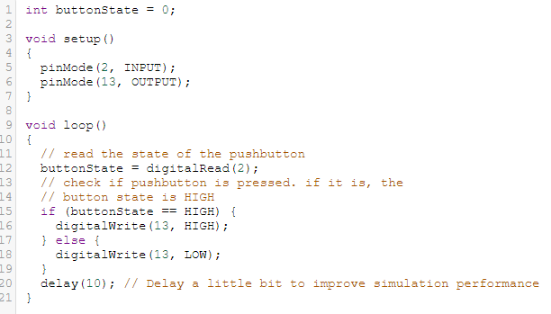
- Run the codes and see what happens when you press the push button.
- Your reflections
- How can Arduino get input?
- Why did the code use digital input?
-
-
-
Learning sensor – Photoresistor
- Build a physical circuit below
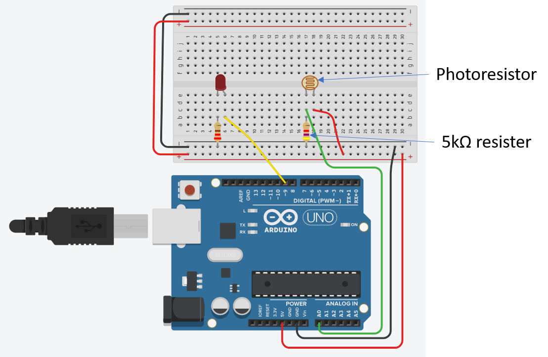
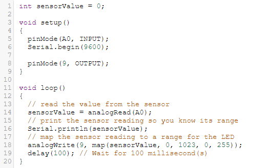
- Write the codes on Arduino
- Upload and test it
- Change the amount of light goes to Photoresistor and see what happens.
- Open Serial Monitor on Arduino [Tools] – [Serial Monitor]

- Your reflections
- In Arduino programming, how can you trace data flow while running it?
- How did this example get input signal? Analog? Why?
-
-
-
An application of Photoresistor, Light Detector
- Built the circuit below by modifying previous circuit.
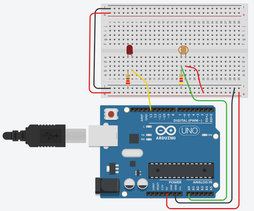
- Write codes below (ignore the commented lines “// this is a comment line”)

- Run your Arduino and see what happens
- Your reflections
- Explain the codes you used.
- If you want to change the sensitivity of the photo sensor, what parts of the codes do you need to change?
- How can you apply this technique into real-world problem-solving?
-
Post-Class
- Weekly Reflection
- What did you learn?
- How will you use the concepts you learned?
- What do you want to learn more?
- Open portfolio
- Review your Open Portfolio.
- Instructor will review and grade your Open Portfolio this Friday.
- Next week
- Oct 19th
- Digital fabrication 3, focused on motors and sensors.
- Design and build an automatic hand-sanitizer dispenser
 This site is licensed under a Creative Commons Attribution-NonCommercial 4.0 International License. You are free to share (copy and redistribute the material in any medium or format) and adapt (remix, transform, and build upon the material for any non-commercial purpose). Under the following terms you must give appropriate credit, provide a link to the license, and indicate if changes were made.

Recent Comments