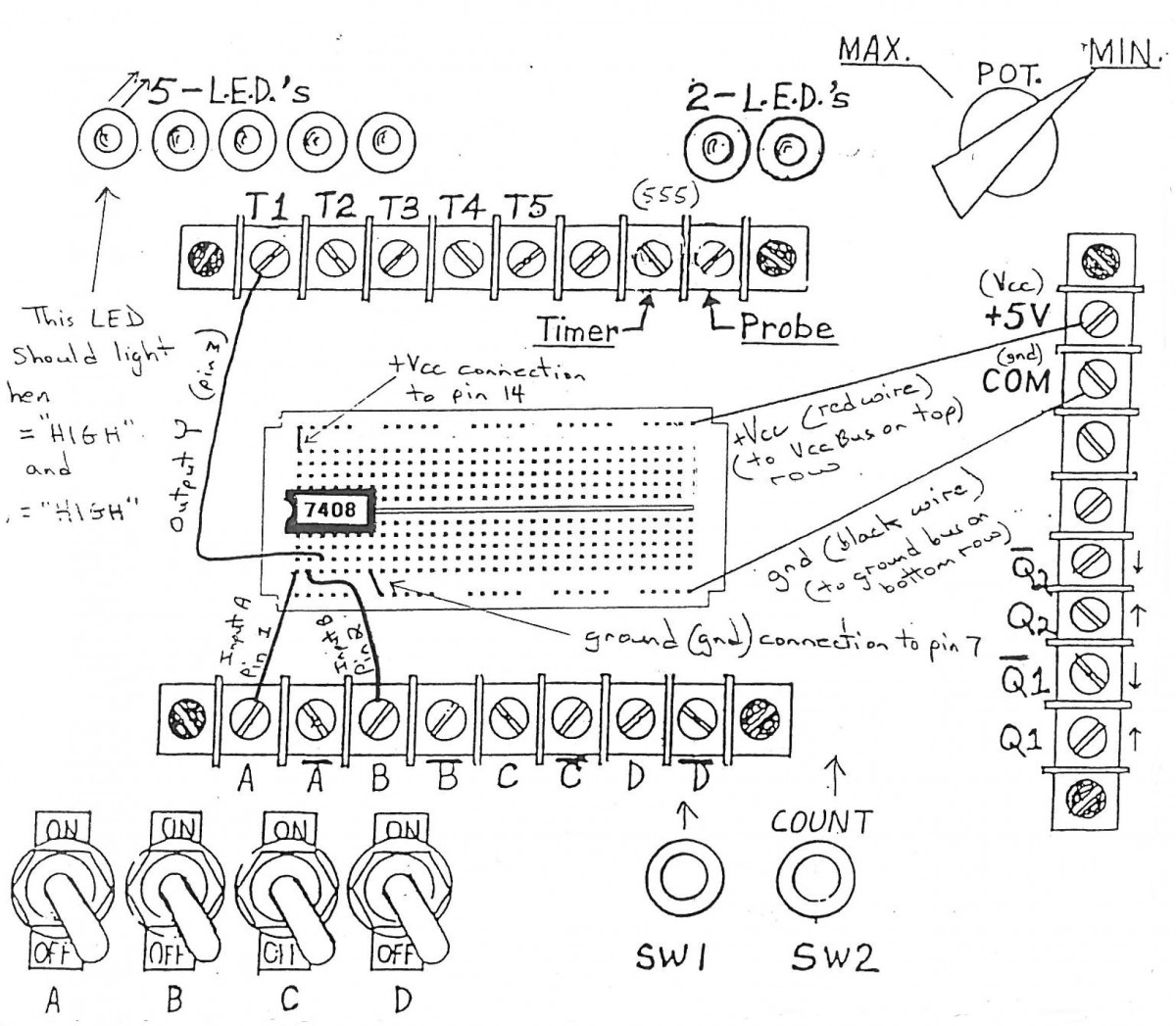
- Inputs: A, B
ON = “High” (up-position)
OFF = “Low” (down-position)
- Output: Y
|
The following problems are listed in order of frequency of occurrence. [1 = most often, 6 = least often] |
|
|
Note: The order in which you check these may vary depending on the situation. |
|
|
Problem 1) |
Bad Wiring |
|
Cause: wrong connection |
|
|
Solution: Check breadboard and/or schematic for correctness and make proper connection(s). |
|
|
Problem 2) |
Vcc and/or Gnd not connected |
|
Cause: Wrong connction |
|
|
Solution: Check this and make proper conncetion(s). |
|
|
Problem3) |
Incorrect Chip Placement |
|
Cause: Chip is placed in breadboard backwards or up side down. |
|
|
Solution: Make sure that chip is placed over center gap correctly and pin 1 is in the lower left corner. |
|
|
Problem 4) |
Pin(s) Bent under |
|
Cause: Pin(s) wer not in placed in hole(s) in breadboard when IC was inserted. |
|
|
Solution: Close visual examination should reveal fault, straighten pin(s) and re-insert chip if faulty. |
|
|
Problem 5) |
Defective Holes in breadboard |
|
Cause: Manufacturing defect, overuse, or usage of oversized wire |
|
|
Solution: Move chip to different part of breadboard and do not use same hole(s) again. |
|
|
Problem 6) |
Bad Chip |
|
Cause: Maufacturing defect which is extremely unlikely or chip has been connected in wrong manner to power supply and has become damaged. |
|
|
Solution: Ask to replace it. |
|
|
If you encounter a problem, do not call the CLT or Instructor unless you have checked all six of the possible problems listed above. |
|
|
Recommended practice: Use RED wire for all Vcc connections, BLACK for all Ground connections, and use as many different colors as possible for the other connections. This color coding of wires helps tremendously when troubleshooting. |
|
|
When wiring circuits on the breadboard make sure the AC cord of your digital trainer is disconnected. This will prevent possible shock hazards and damage to the integrated circuits. |
|
|
FYI: Vcc=5.25 Volts, IC = Integrated Circuit [or “chip” for short], TTL = Transistor-Transistor Logic(74XX), for all logic gates [7408=AND, 7400=NAND, 7432=OR, 7402=NOR gate] Vcc=> pin 14 and Gnd=>pin 7 in TTL. |
|

