Contents
Equipment/Parts Needed
- 5V DC Power Supply
- Digital Trainer (Logic Probe)
- Breadboard
- DIP Switch
- 7400 NAND gate
- 7402 NOR gate
- 7404 Inverter
- 7408 AND gate
- 7432 OR gate
Objective
- Many times in the application of Boolean algebra, you have to reduce a particular expression to its simplest form or change its form to a more convenient one to implement the expression most efficiently. The approach taken in this lab is to use the basic laws, rules, DeMorgan’s theorems, and theorems of Boolean algebra to manipulate and simplify an expression.
- After performing this experiment, you will be able to simplify a combinational logic circuit to its minimum (simplest) form.
Discussion
- The basic rules and laws of both Boolean Algebra and DeMorgan’s theorem are used to reduce a given expression to a simplified form so that the number of gates are minimized to as far as possible to produce the same output.
- A Truth Table defines how a combination of gates will react to all possible input combinations.
- A Logic Probe is a piece of test equipment which displays the logic level at a point in the circuit. 0 to 0.8V = Logic 0 and lights the L indicator. 2.0V to 5.0V = Logic 1 and lights the H indicator. Invalid logic voltage levels light neither indicator.
Part 1
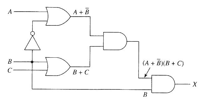
1) Construct a circuit whose expression shown in Figure 4-1 using AND and OR gates.
2) Find the Boolean equation for Figure 4-1.
3) Fill in the Truth table and measure the voltages of VA, VB, VC, and VX for each input/output.
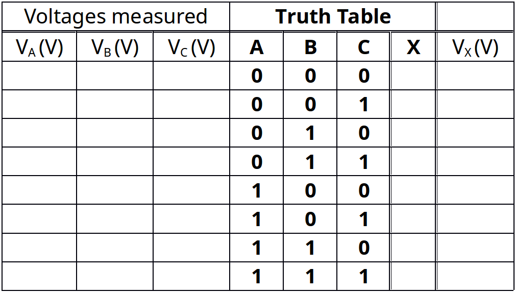
Table 4-1 Truth table and volts measured for input/output for Figure 4-1
4) Simplify the expression and circuit for Figure 4-1. Verify that the simplified circuit is equivalent to the original by showing that the truth tables are identical.
- The simplified expression is:
- Draw the simplified circuit here.
- Develop the truth table for the simplified circuit and measured the voltage for each input/output.
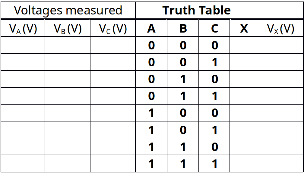
Table 4-2 Truth table and volts measured for input/output for the simplified circuit of Figure 4-1
- Verify the truth tables Table 4-1 and Table 4-2 and show they both are identical.
Part 2
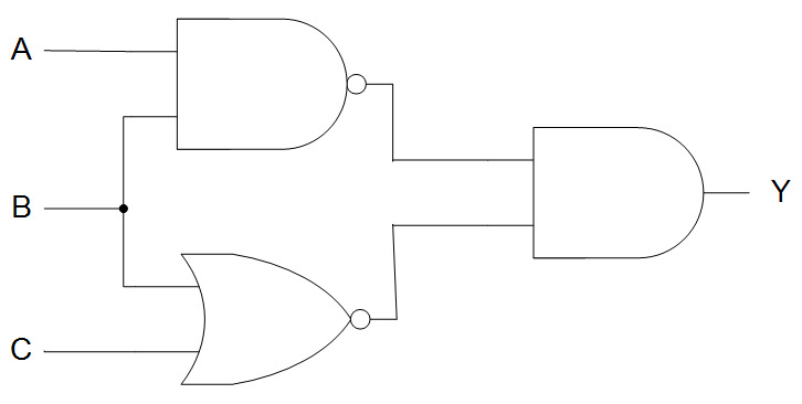
1) Construct a circuit whose expression shown in Figure 4-2 using NAND, NOR, and AND gates.
2) Find the Boolean equation for Figure 4-2.
3) Fill in the Truth table and measure the voltages of VA, VB, VC, and VY for each input/output.
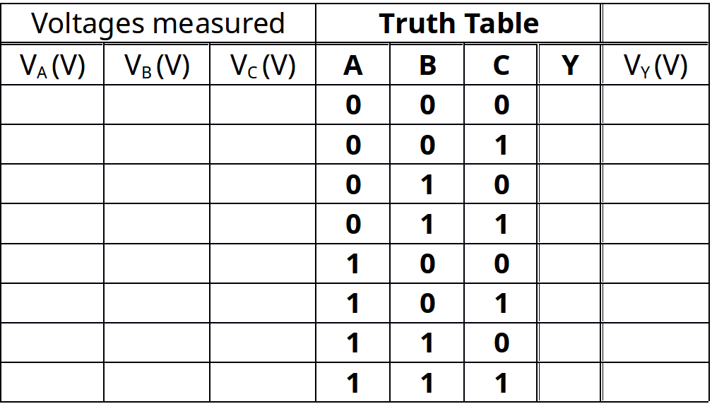
Table 4-3 Truth table and volts measured for input/output for Figure 4-2
4) Then simplify the expression and circuit, and verify that the simplified circuit is equivalent to the original by showing that the truth tables are identical.
- The simplified expression is:
- Draw the simplified circuit here.
- Develop the truth table for the simplified circuit and measured the voltage for each input/output
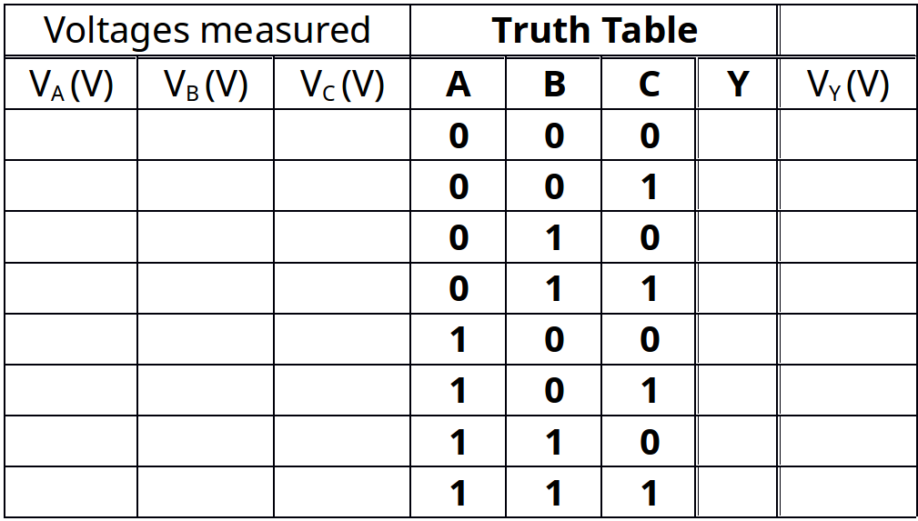
Table 4-4 Truth table and volts measured for input/output for the simplified circuit of Figure 4-2
- Verify the truth tables Table 4-3 and Table 4-4 and show they both are identical.
Part 3
1) Construct a circuit whose expression shown in Figure 4-1 using NOT, AND and OR gates.
2) Find the Boolean equation for Figure 4-3.
3) Fill in the Truth table and measure the voltages of VA, VB, VC, and VX for each input/output.
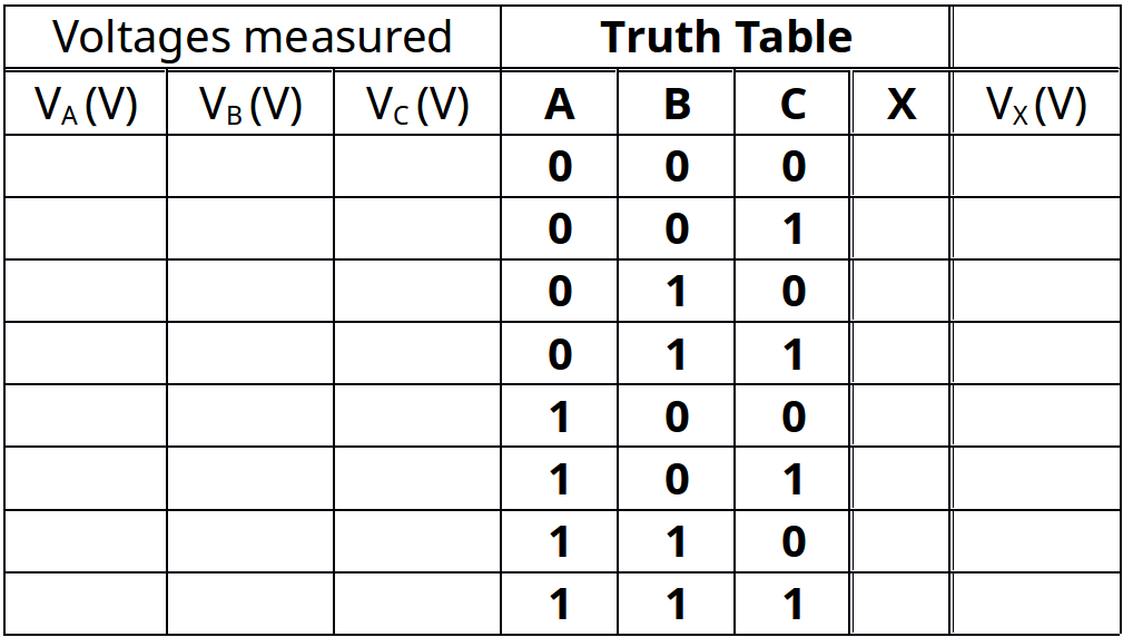
Table 4-5 Truth table and volts measured for input/output for Figure 4-3
4) Simplify the expression and circuit for Figure 4-3. Verify that the simplified circuit is equivalent to the original by showing that the truth tables are identical.
- The simplified expression is:
- Draw the simplified circuit here.
- Develop the truth table for the simplified circuit and measured the voltage for each input/output
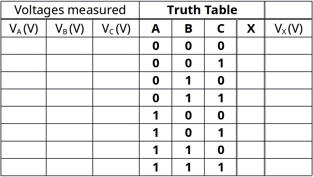
Table 4-6 Truth table and volts measured for input/output for the simplified circuit of Figure 4-3
- Verify the truth tables Table 4-5 and Table 4-6 and show they both are identical.
Questions/Report
- Why is Boolean algebra used for combinational logic circuits?
- What are three laws for Boolean algebra? Answer with simple examples.
- Why is De Morgan’s theorem important in the simplification of Boolean equation?
- Using De Morgan’s theorem, you can prove that a NAND gate is equivalent to an __________ (OR or AND) gate with inverted inputs.
- Using De Morgan’s theorem, you can prove that a NOR gate is equivalent to an __________ (OR or AND) gate with inverted inputs.


