Monthly Archives: April 2013

Assignment 08

Assignment 08

DESCRIPTION

Toolpath your surfaces from Assignment 07 in RhinoCAM. Follow the videos provided below and use the Rhino template and CSV tool set file provided on the Course Files page. You will be expected to perform a comparative toolpath study for the finish toolpath using a matrix of 3 tool types (3/8″, 1/4″, and 1/8″ ball) and 3 stepover settings (75%, 50%, and 25% of the tool diameter).

REQUIREMENTS

Come to class on May 1st with your RhinoCAM file completed through the roughing and finish toolpaths and a completed toolpath study performed using the InDesign template provided on the Course Files page.

SAMPLE TOOLPATH STUDY


RhinoCAM Basic 3 Axis CNC Toolpathing Strategy


Assignment 07

Assignment 07

Description

Generate surfaces in preparation for RhinoCAM.  Using the image map component tutorial from last week, create two surfaces from images.  Don’t just download an image from the internet, but design one in photoshop/illustrator.  Keep in mind that gray scale images tend to work best and images that have a gradual change in contrast from black to white areas.  Also, feel free to experiment with different photoshop effects and filters.  Hint: you might want to use the Gaussian blur.

Requirements

Come to class on April 24th with your two surfaces and the images you used to create them.  You will be using them in the RhinoCAM tutorial.  Make sure they fit on the template file and that the surfaces fit in a 16″ x 16″ x 2″ volume.

Scoring

  • Design : 60%
  • Demonstrates Proficiency with Tool: 20%
  • Labeling /Organization of Dropbox and definition/ Correct File Naming: 5%
  • Followed Assignment Directions: 15%


Resources

Check out these resources for more info on the responsive components and the laser cutter assignment.

Week ?: Image Map Component


Assignment 06

Assignment 06

Description

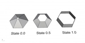
Fabricate your responsive component.  You should now have a responsive component in Grasshopper that responds to an input parameter control with a range of 0.0 to 1.0.  Using the laser cutter as your fabrication technique create 3 versions of your component that represent 3 unique states of your component.  You can choose any 3 values from 0.0 to 1.0 or you could use the end and middle conditions, for example 0.0, 0.5, 1.0.

Continue reading