Problem #4 F2M

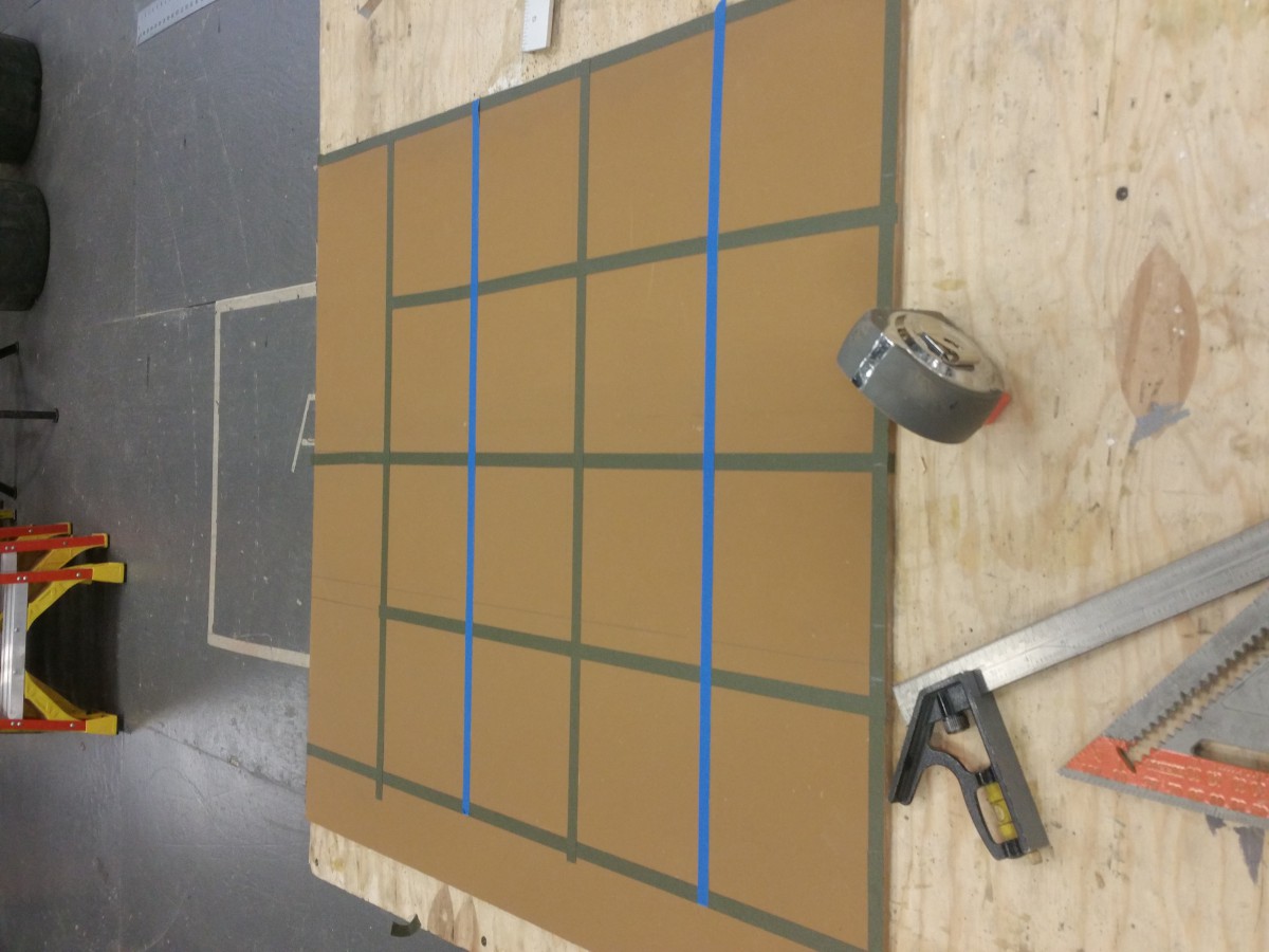
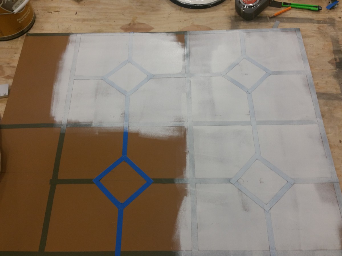
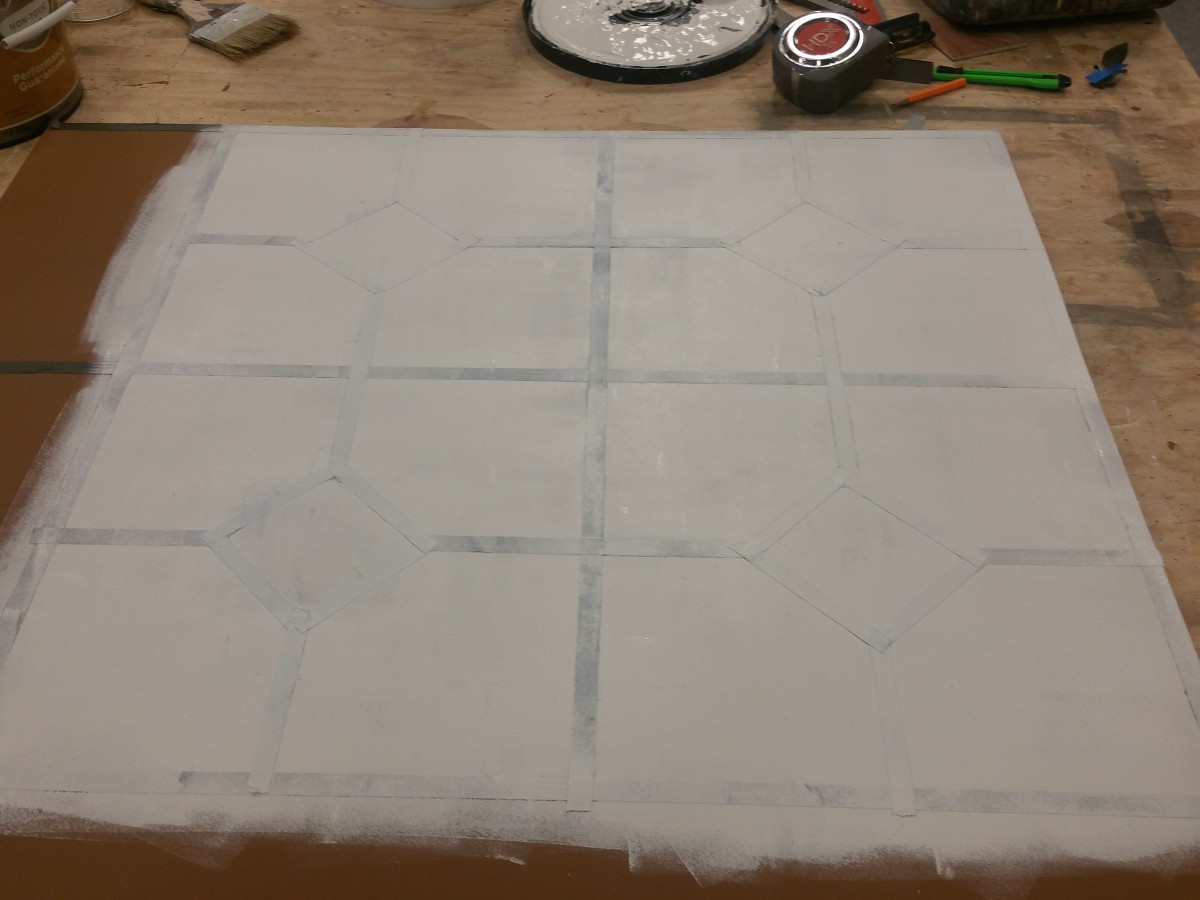
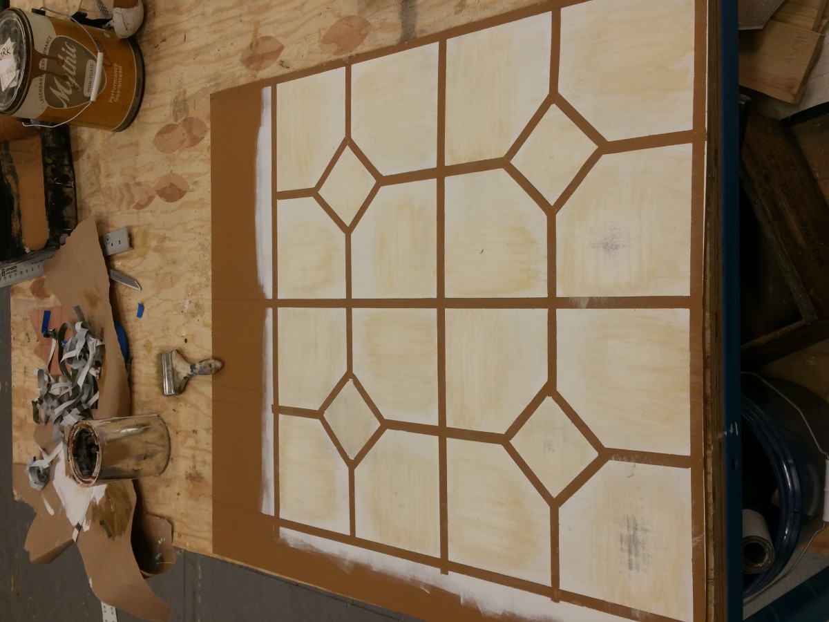
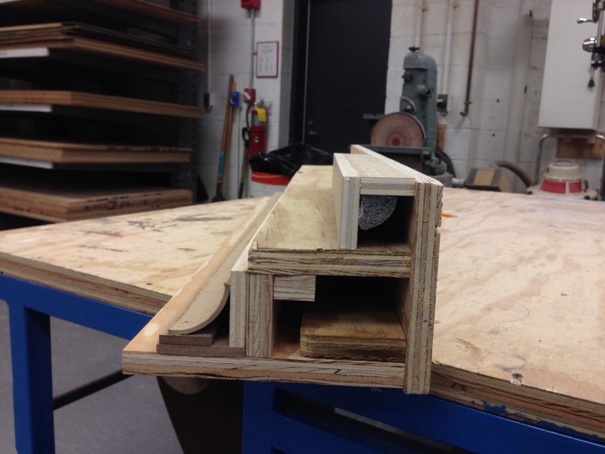
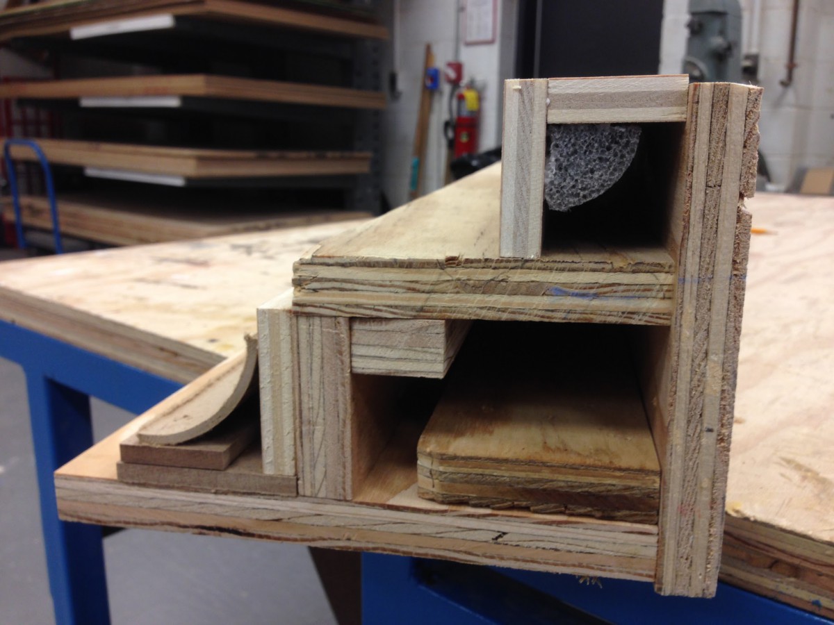
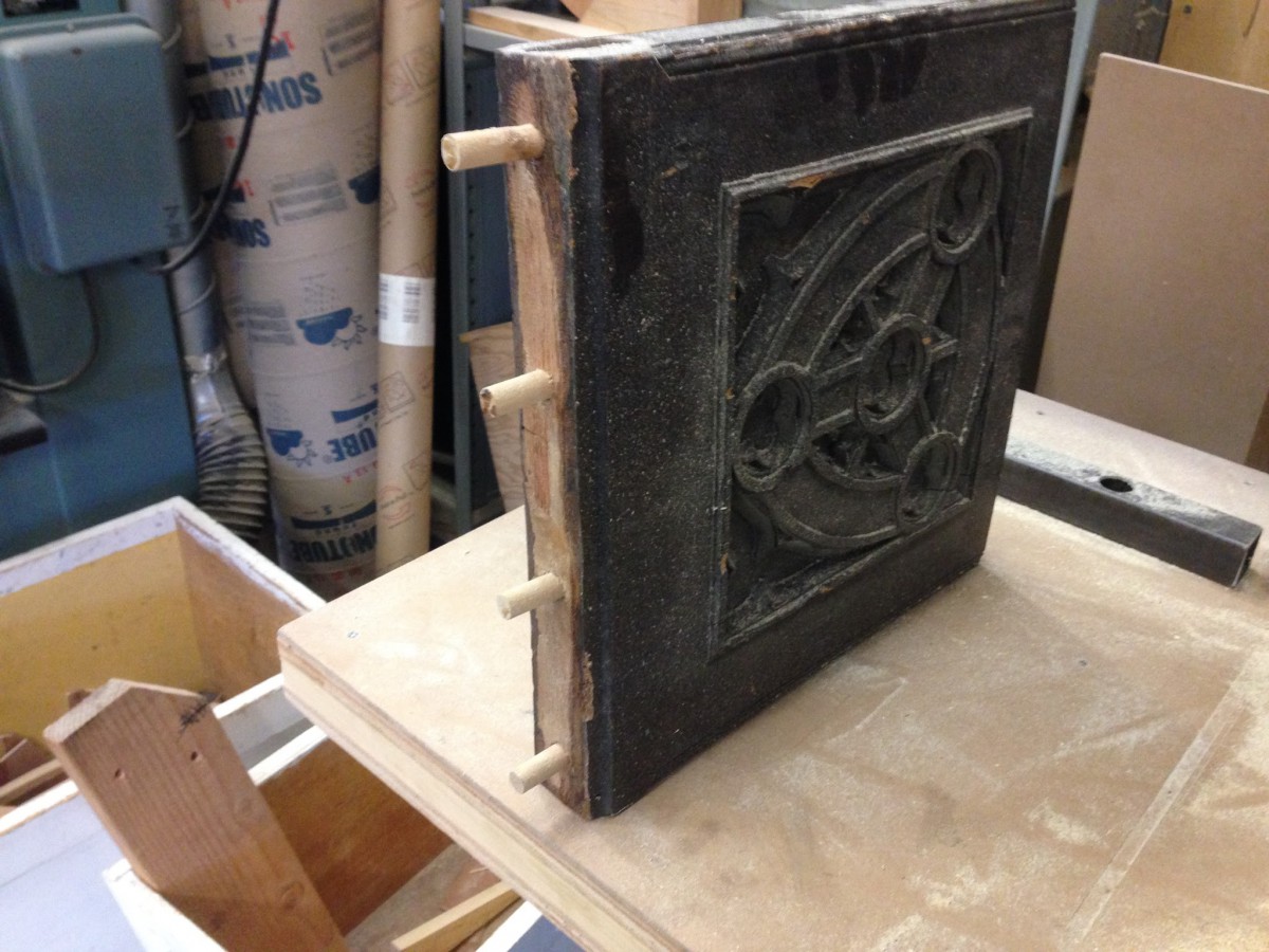
For problem #4 I teamed up with Andrew and Briana to recreate an apartment set based on the play F2M.  The set was very intricate, so we broke up tasks based on strengths. Since our project was based on specific designer drawings and hired labor, we believed the definition of the problem was recreating set materials on a smaller budget, while keeping labor time to a minimum.  I took on the tasks of doors, windows, mouldings, brick wall and kitchen floor.  My goal was to try and save money and be as efficient with labor time as possible by coming up with DIY alternatives for as many items as I could.  The windows were ordered via a home supply store.  For the doors, plain faced hollow cored doors would be used.  Trim moulding would then be attached to the face to create the decorative effect seen in the designer drawings.  For the kitchen floor I decided to paint it as it was hard to find the pattern requested in the specific color mentioned.  Taping off MDF to create the desired pattern and faux painting the requested colors seemed like the best option.  Although tedious, it makes up in expense and will provide the designer with exactly what he/she is seeking. The crown moulding would also be ordered from a home supply store, but the brick wall was definitely a DIY project, in order to achieve the look requested.

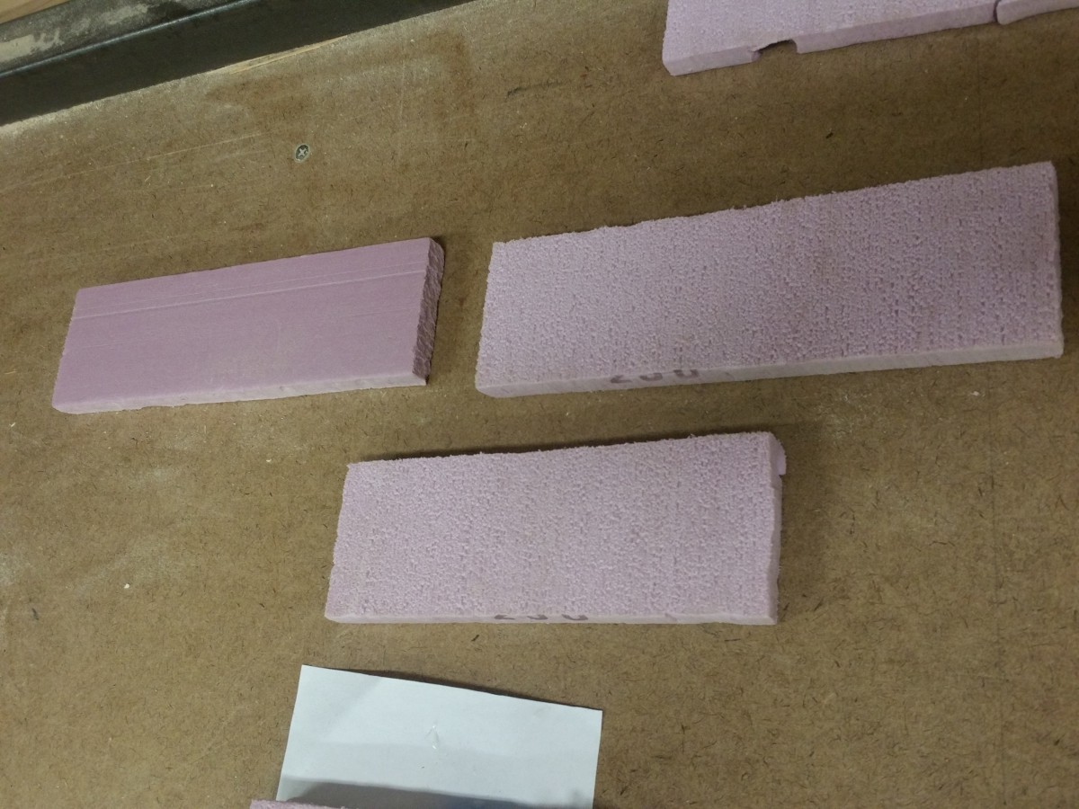
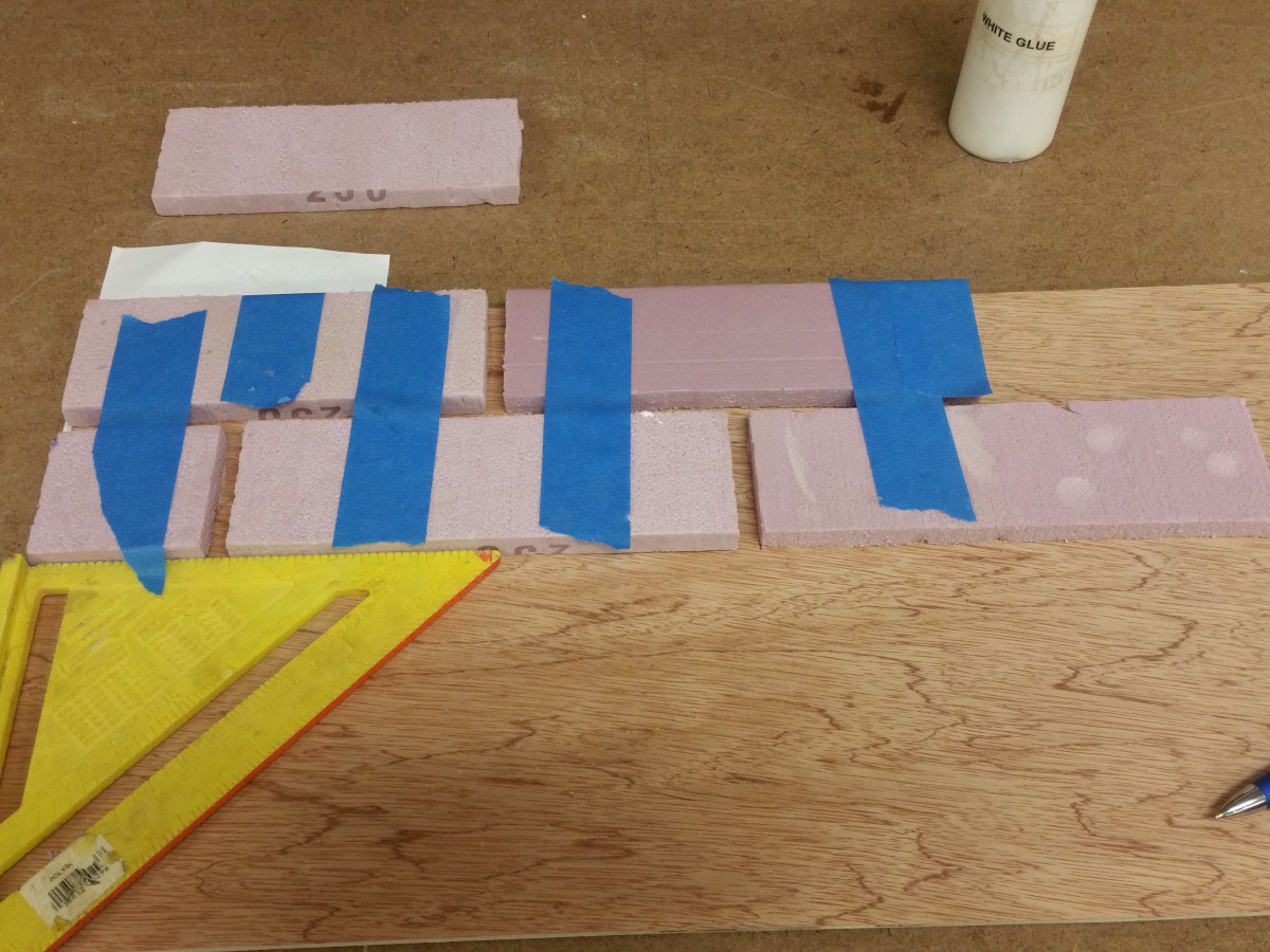
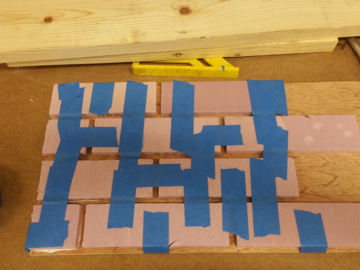
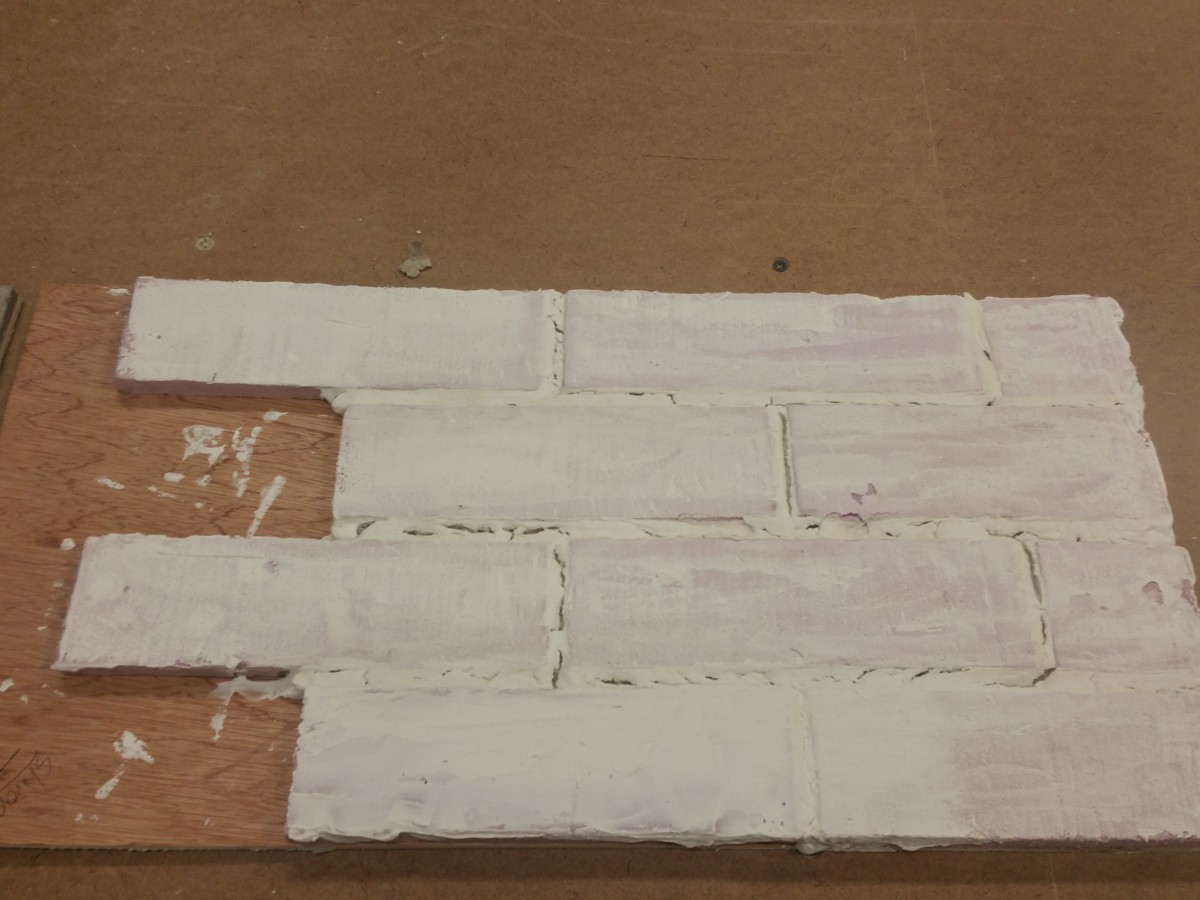
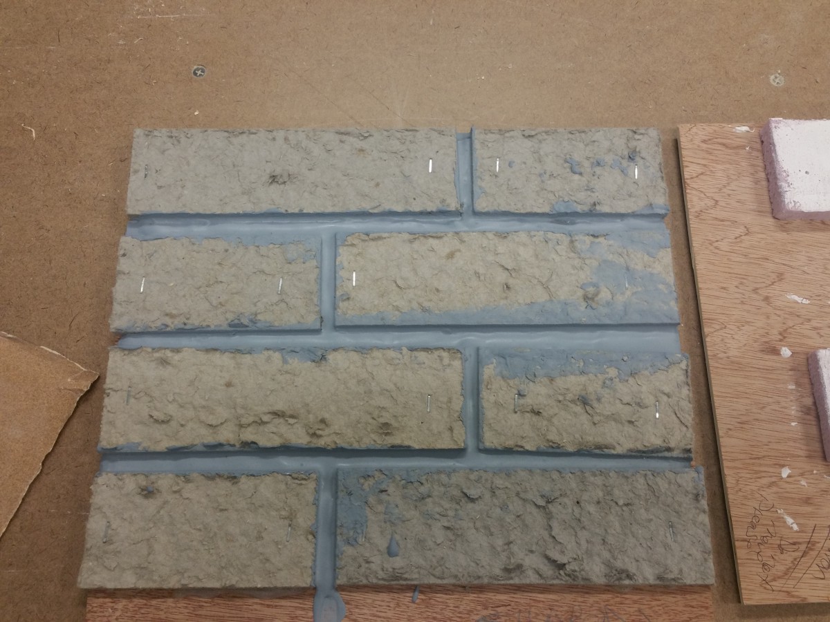
For the Brick wall, I researched daily.  I viewed numerous videos and read various book articles.  I also used some of my prior experience to try and create a brick wall alternative.  I tried fake bricks cut out of foam with faux grout created out of joint compound, white glue and water.  The bricks worked well, but the grout cracked horribly. I realized my bricks were to thick and played a roll in the cracking of the grout.  Therefore, I tried using bricks split from homasote board and created another grout mixture.  This time the grout mixture was joint compound, latex paint, water and glue.  The brick effect looked much better using that method.  However, the grout began cracking a little as well.  I learned later it may have been to me placing water in the mixture.  Next time around, I will probably just use actual grout.  That probably would work just as well.


I believe the use of unconventional materials to create conventional items will also play a role in my real life experience as I build a lot of props and mini background sets for my photography business.  I learned a lot about mixing materials and faux finishing during this project.  I also learned a lot about the value of time.  I would definitely had planned my time better when creating my projects as they were very tedious and took a lot of time to figure out.  That is something I can also take with me in real life on the field when it is time to delegate tasks and purchase materials.  Time will play a role in all of those decisions.


20160517_182811 20160517_182827 20160517_185332 20160517_185735 20160517_192344 20160503_171937 20160503_172017 20160503_173621 20160517_182834 20160517_182840 20160517_182926

Posted in Uncategorized | Leave a comment

Problem #2 Deck (Reflection)

Sharon Miller

Technical Direction

ENT4410

Problem #2 (Deck)


How do you know the things you believe you do?


Using our prior class projects as examples, I first define what the actual problem is to determine my direction. Afterwards, I use research and prior experience to determine my knowledge on a particular subject or project. I also read books, research online, compare materials and their usage. If needed, I sketch out my ideas and create a prototype to see if my ideas are plausible. I then analyze what I have done and try to figure out how to improve upon it.


Project Analysis (Problem#2)


For our last project, we had to create a deck for two shows, a concert and a talent show. Both events scheduled to take place in the Voorhees theatre. After reading through the documentation, my first thought was the main priority would be scheduling time. My initial focus was creating a schedule that would allow the crew to build, strike an install the deck on time. I later realized the focus although still time based, needed to really be on the deck itself as the build of the deck would dictate how the schedule created.   I felt having a raked open frame would work best over triscuits as the triscuits would need too much time to figure out placement. The open frame would be sturdier and faster to install. Upon later thought I realize I should have focused more on how many crewmembers were available and the amount of time it would take to build each frame. I thought more on the end result and not the amount of physical manpower needed to get there. Had I done that, I would have more thoroughly broken down the amount of frames needed, the specific work hours, the actual amount of staff required and how these individuals would work in a shared shop.  I feel the lessons learned during the project will help me in real world scenarios, because it will help me calculate accurate schedules, whether in school, theatre or at work. I have learned that time management of a project is more important than everything and dictates the success of the project completion.


My Original Project Schedule Notes:

  • Haunted Hotel strike must be completed by end of call on Thursday
  • Concert takes place 8 days later on Friday at 8pm
  • Talent show is Saturday
  • Talent show rehearsals begin Saturday at 4pm
  • Talent show begins at 8pm
  • Tech Production Hours: Monday & Wednesday 2pm-5pm
  • Friday Concert Ends 10pm
  • 12 Crew Members
  • Extra Crew Hours Available
  • Band wants logo on floor
  • Floor must be glossy black for talent show
  • Platform stairs must be matte black


SCHEDULE LIST


  1. Thursday: 2pm – 5pm, Haunted Hotel Strike
  2. Monday: 2pm-5pm, building of platform frame and stairs
  3. Wednesday: 2pm-5pm, completion of platform frame and stairs, stage floor pieces and stairs painted (glossy paint for stage & matte for stairs)
  4. Thursday #2: EXTRA CALL DAY (all 12 crew members): 2pm-5pm, Stage Platform & stair Installation, temporary vinyl logo application of band logo
  5. Friday: stage already installed, Live Concert begins at 8pm until 10pm
  6. Saturday: 9 AM call (6 crew members), removal of the vinyl logo, paint retouching and stage repair if necessary
  7. Saturday: 4pm rehearsal
  8. Saturday 8pm Talent Show
  9. Monday #2: Crew Call 2-5pm Strike of Stage, stairs and scenery


Posted in Uncategorized | Leave a comment

April 12, 2016 Class Notes – Budget

What is a budget estimate?

-Everything you think you need for the production. When making a rough estimate, know that it will change over time. Last minute ideas and new solutions to problems will cause these changes.

When does change occur? – During build, during tech, during anytime; mistakes happen that 10% contingency does not account for.
You have to revise your budget, or improvise accordingly.
10% contingency doesn’t cover big changes.

-Creating the budgeting process should be the hardest part of your whole project. It is your plan that you will always be following and referencing. If you’ve done it correctly, then you can easily execute your plan.

-You should be around 90% confident in your budget before submitting it. Luis was 75% confident on his curved moulding building method before actually building it. He was then 0% confident in it after seeing how it turned out.

-Going under-budget is just as bad as over-budgeting. It means that money is potentially being cut from other departments to tend to your budget. It also means that your planning wasn’t accurate.
“For every show, there is a $500 version, $1000 version, $5000 version, etc.” -McCullough

If you’re over-budget, look at how the money is allocated, and look at all the big numbers first. See how you lower those numbers.

-Director, designers, production manager, department heads, producers will all be present at the budget meeting. The producer wants the bug picture; total budget. The designer wants to know materials used, aesthetics. Director wants to know how the set will help with the storytelling.

How can you tell what the producers want for the show? You can ask them, see how much they mention it, or see how much money they’re willing to spend on it.


The class ended by discussing how each group divided up their materials for their budgets.

Posted in Uncategorized | Leave a comment

Wire Curved Crown Moulding

IMG_0126 IMG_0132 IMG_0133 IMG_0124 IMG_0125

After observing most of everyone’s method of building the curved crown moulding, I tried to find a way to make it lighter, more efficient and maybe even more experimental just for fun and I believed working with chicken wire was worth the risk. I had reasonable hopes for it having used it before but slowly as we built it we realized it was not going to work at all. Chicken wire is absolutely more reliable for organic shapes like trees and rocks, not necessarily useful for uniform shapes that need to be consistent all the way around.

Posted in Uncategorized | Leave a comment

Problem 3 Wallpaper Patter

Wallpaper Sample

This is the wallpaper sample from the designer. This image should scale up to 2′ x 2′ for the show.

Posted in Uncategorized | Leave a comment

wall paper pattern

hey, professor, what is the the pattern for the molding?

Posted in Uncategorized | Leave a comment

3 dimensional curved cove molding

I have modeled and extruded samples  of curved cove molding.

I limited the size to  2 square feet to fit on the working CNC machine.

To make a 3d curved extruded object, draw the object you want as a closed poly-line. Then draw the path you want it to follow as a line or poly-line. Enter the (Sw)eep command, select your object(s) , enter ‘B’ and select a (B)ase point, and finally pick the path you want it to follow.

Orientating which side of the path the base point is drawn against took some trial and error.

CAD and STL files Files linked below:

https://onedrive.live.com/redir?resid=7A6786754F96D937!40915&authkey=!ADwfd7XRbwJEiTw&ithint=folder%2c


2x2 convex cove moulding 2x2 concave cove molding

The size limitations for architecture’s working CNC machine are actually 14.8 to  15 inches square with the current bed configuration. The test sample needed be scaled accordingly and exported to Rhino.

rhino bed size

Objects must be saved in their own cad file (without references to title-blocks) to open smoothly in Rhinoceros 5.0. Then the selected object can be exported as an SLT file.

convex cove rhinoconcave cove rhino

Then they can be imported to architecture’s template.

Link to Architecture’s page: http://www.nycctfab.com/#!equipmentcncmachining/c7s5

At the bottom of the page there is a folder, “NYCCTfab Template Files,” where you can get the “NYCCTfab_Roland_Standard_3Axis_pallet.3dm file to set up the CNC tray.” Import your STL file into the template and contact architecture to set up an appointment.

Appointments can be found in http://www.nycctfab.com/#!cnc-monitor-schedule/c1sh6

Update

Since the CNC lab only has 1.5 inch wood bits until they can buy replacements, the 2.5 inch curved cove had to be cut in half and laminated later.

IMG_2925 IMG_2919 IMG_2923

The CNC Roland machine is capable of routing a 16″ by 16″ sheet or block of plywood.

Tool paths can be adjusted to have more steps for more pierces definition to your virtual model, but this comes at the expense of more time for more passes and wear to the bit.

Software crashes hardware errors are inevitable but can be planned around.

Sample video:

The final piece came out a little rough but satisfactory the project.


Posted in Uncategorized | Leave a comment

Crown molding profile prototype

Working on making a sample section of crown molding for the straight sections of wall.

We boxed out the main sections with 3/4″ plywood then made a cove with quartered tube and strips of material to see how building up cove molding with layers would look.

the smaller cove did not a cardboard tube available to sample so a composite negative form was made and will be tested with the vacuum form to see if it can be scaled for the rest of the flats.

Observations from other pieces in the shop made me want to investigate other methods of attaching molding including drop-pegs and fixed crown molding.

Quarter tube cove on boxed out molding frame. It’s still pretty heavy per foot, may use lighter materials for interior minor surfaces.

IMG_2899 IMG_2900 IMG_2901

Quartered foam round to form vacuum form negative.

IMG_2902 IMG_2903

Haunted hotel fixed crown molding on curved wall flat.

IMG_2904

Piece with pegs to be dropped into slotted piece.

IMG_2897 IMG_2898

Cove Molding

The 2 inch radius cove had to split it into 2 pieces that would be combined later. I set up the angled fence with the speed square gauge on the table saw and used a jig to maintain pressure. All measurements for the cove cheat-sheet are all done in millimeters, and units should be converted accordingly.

Even though, the cove came out mostly even, it still had a few heave grooves from the unevenness of the lumber and uneven vertical pressure from the some of the passes.

IMG_2909 IMG_2908IMG_2907

IMG_2910


Posted in Uncategorized | Leave a comment

curve molding

So I have received the suggestion to try building the curve molding out of plywood wood layers. each layer would have a an out side radius of 3′-0″ and a inside radius of 2′-6″. To start off we cut out one piece and then used that piece to route out 13 to 15 at a length of around 2′-6″(we wasn’t really focused on length as the test is to see if we can get the profile of the moding) these pieces would then get cut to a smaller width, as shown in the pictures below, and then we will layer them to get the molding profile. I used the drawing that McCullough gave to us as a way to measure and break down the molding into 1/2, 3/4, and 1/4 inch thickness, for materials we used plywood, lauan, and MDF.20160315_174350 20160315_174343 20160315_174336 20160315_174326

Posted in Uncategorized | Leave a comment

Vertical vs horizontal lauan on curved flats test

We built 2 frames at 4 feet tall with 3 foot radius to compare and contrast construction methods.

The convex flat was ran a continuous piece of lauan across the arch length. While, the concave flat used the 4 foot width of the lauan and needed a toggle seam to complete the arch.

We observed that 1/4″ lauan is more flexible perpendicular to the surface grain because the internal structural ply, while it was harder to manipulate the ply to curve with the surface grain, it was not impossible. Lauan can be purchased with different directions of grain depending on the lumber order.

  • shaping toggles and rails to have styles line up perpendicular to face makes it easier to install styles without mitering them to be flush to face.
  • Since there is no access to the edges of center seam catcher toggles, they need to be stapled in to nailing blocks.
  • Not using top and bottom rails and just using toggles means fewer custom pieces for the flats and gets more use out of the existing templates.
  • Cutting the lauan with an overhang and routing flush is better than measuring the approximate arch length and makes the edges look uniform.
  • Joint compound helps mask seams and staples for a smooth surface.

I have concluded that facing curved flat with sheet laid across the arch is easier than installing seam catchers.

Pictures linked here:

https://onedrive.live.com/redir?resid=7A6786754F96D937!40887&authkey=!AJHWe-cd4UYmTmc&ithint=album%2c

rails and framing toggles.


20160310_221602446_iOS 20160310_224343253_iOS


On-face 1 by seam catcher and nailing block.

20160312_175754508_iOS 20160312_175800324_iOS 20160312_181312319_iOS

Trim routed edge and guild. Small gap in seam.

20160312_201401151_iOS20160312_201707751_iOS

jigsawed template and routed toggles. Skinned with continuous lauan.

20160312_175805936_iOS  20160312_184757263_iOS  20160312_201421937_iOS


Posted in Uncategorized | Leave a comment