Agenda
Going over Hw 6/7
Hardware –Uses and Application
Hw 8 and Lab Time
Hw 6
Review
Powered rigging
Dead haul – no counterweights/// uses winches to load and unload the weigh
Benefit is you don’t need to unload and load
Brute force – Big motor and safety features
Powered counterweight- counterweight with motor replacing people power
EX: Elevator are counterweight systems
Fixed speed: Only controlled on one speed (cheaper)
Variable speed: multiple speed – Ex show time (match tempo/// more money and programming time)
Money = Material or workmanship quality
Hw 7
Review
Different types of truss
Class
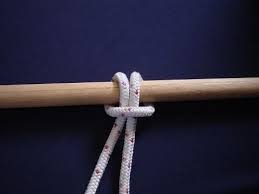
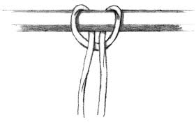
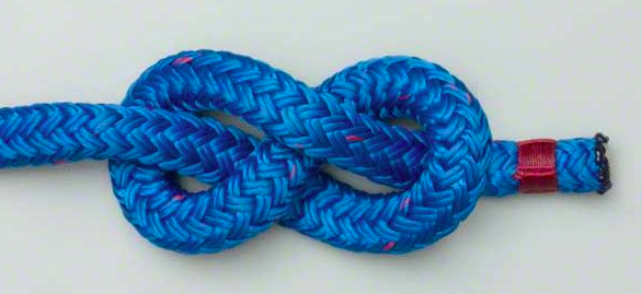
Bowline knot
Over hand
Start with an overhand loop
End of line up through back, behind standing part and behind the loop again
Tail will be in the middle of loop
Ok when loaded and unloaded
Better in more flexible ropes
If you tie it backwards, so the tail is on the outside, you can capsize the know and it will become a slip knot
Bowline is one of the most important knots to know, also clove hitch and figure eight
Should be able to tie any circumstances, rain or shine
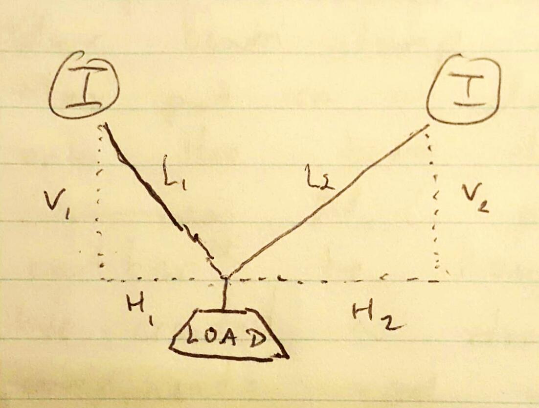
Hardware for top to bottom, how to choose
Ex (fig 1.0) start with a batten at the top
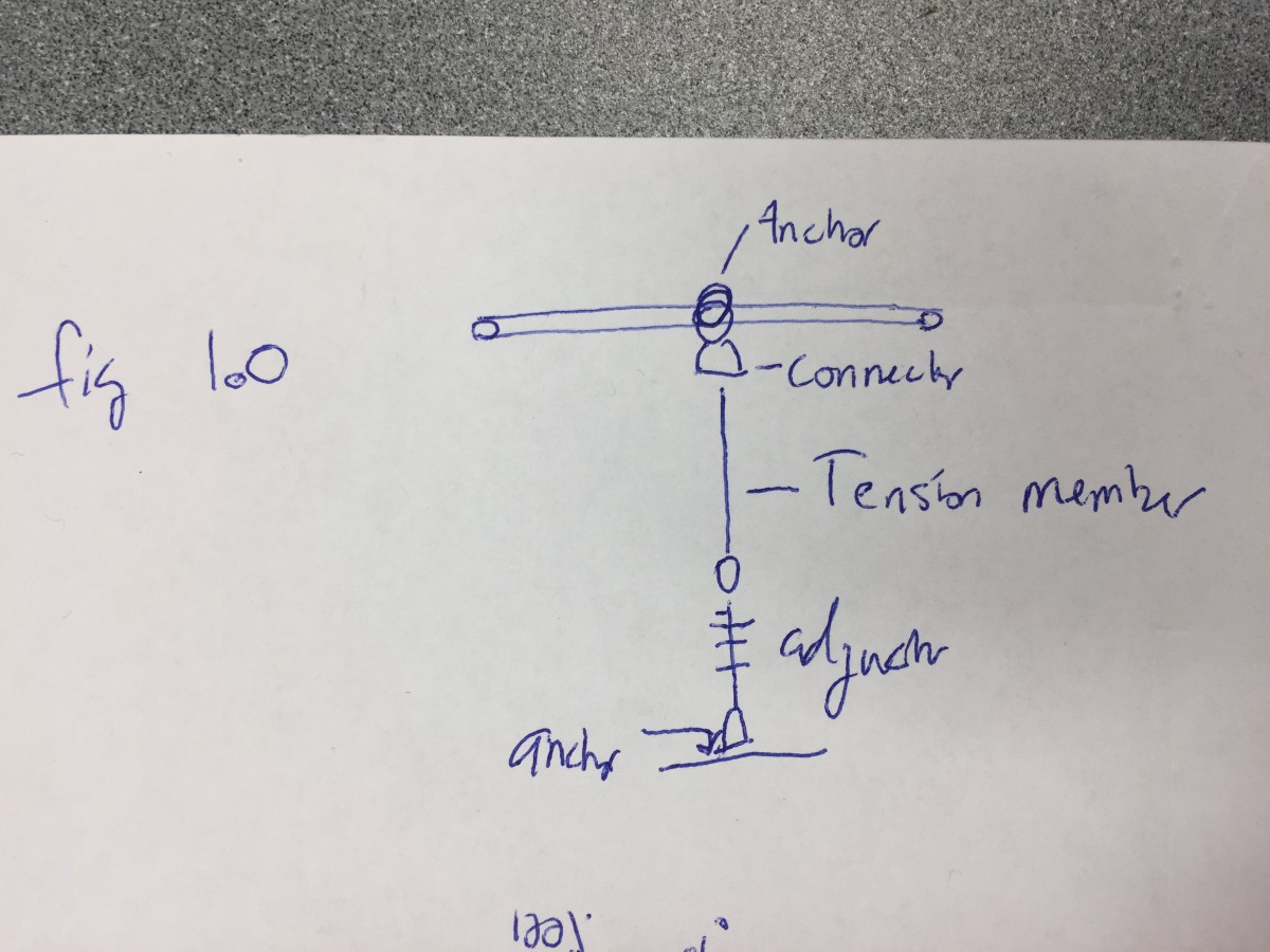
Anchor- how are you grabbing the building or scenery
Connectors – shackles, pair rings, (devices that are designed to connect different members)
Tension members- ropes, cables
Adjustor – change the length, making something level
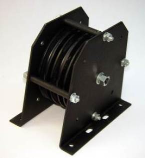
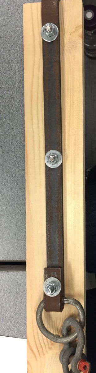
Example Picture 1.1
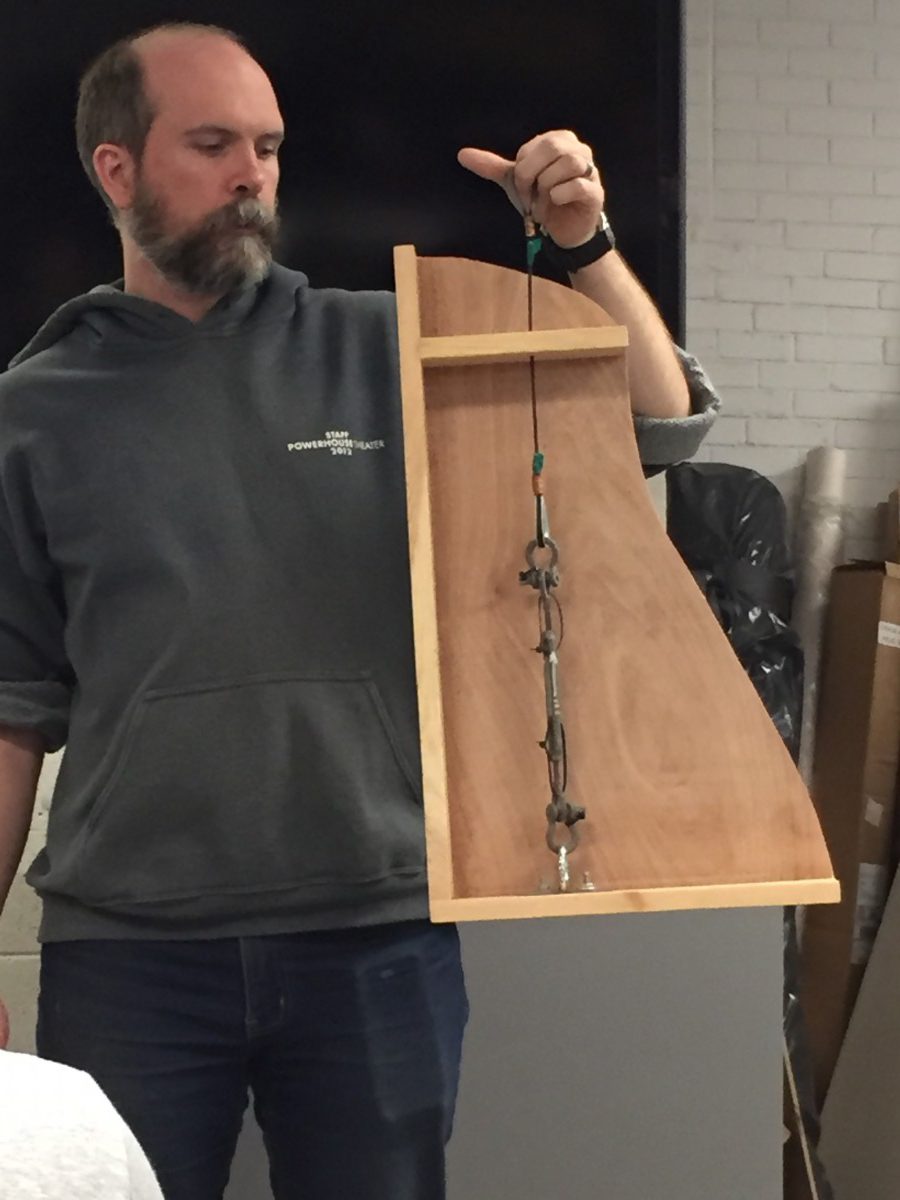
D ring plate through bottom plate (flat thinks it is sitting on the ground, no added stress and much stronger setup than if bolted to the top)
-Attach rigging at the bottom
Anchor-
Things that attach to scenery:
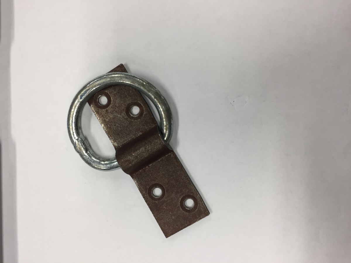
Standard D ring and plate (very convenient, super cheap, no special tools, common in 20th century when scenery was light) Not rated and should not be used for rigging (Picture 1.2), need to drill out hoes to mount)- very common
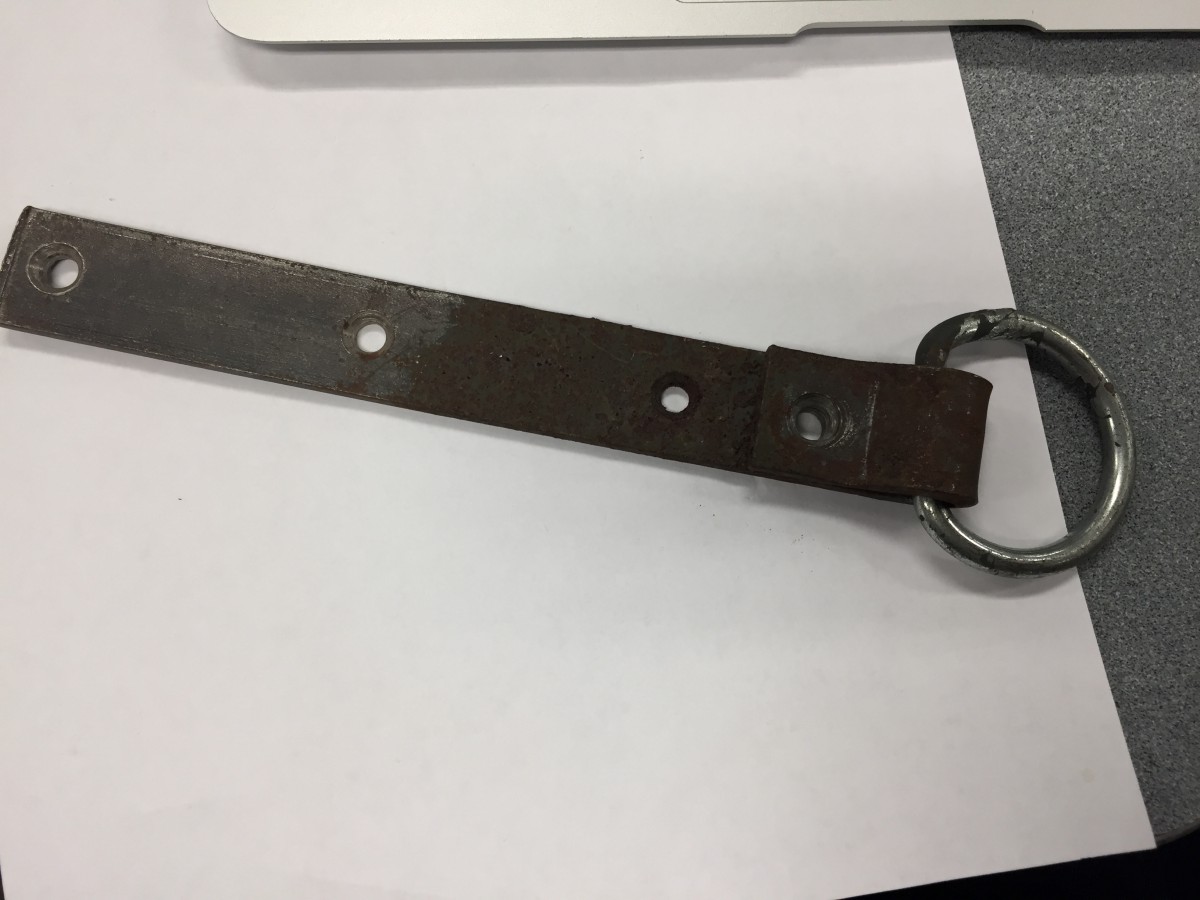
Top hanger iron: Run cable so the flat couldn’t move away from wire, only use is for theatrical flats. (Picture 1.3)
Bottom Hanger Iron: (Picture 1.4)
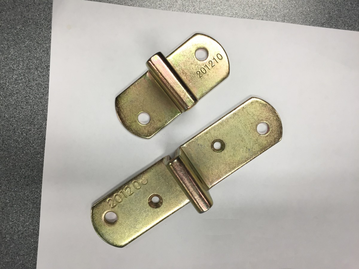
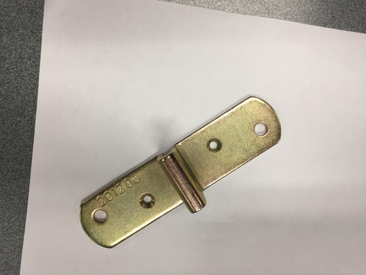
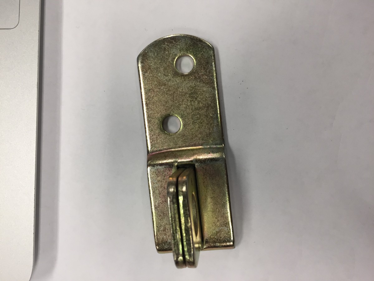
Alternatives to D- Ring and plate: shackle plate, rated. Look at manufacturer spec. Fairly cheap and reusable (Picture 1.5-7)
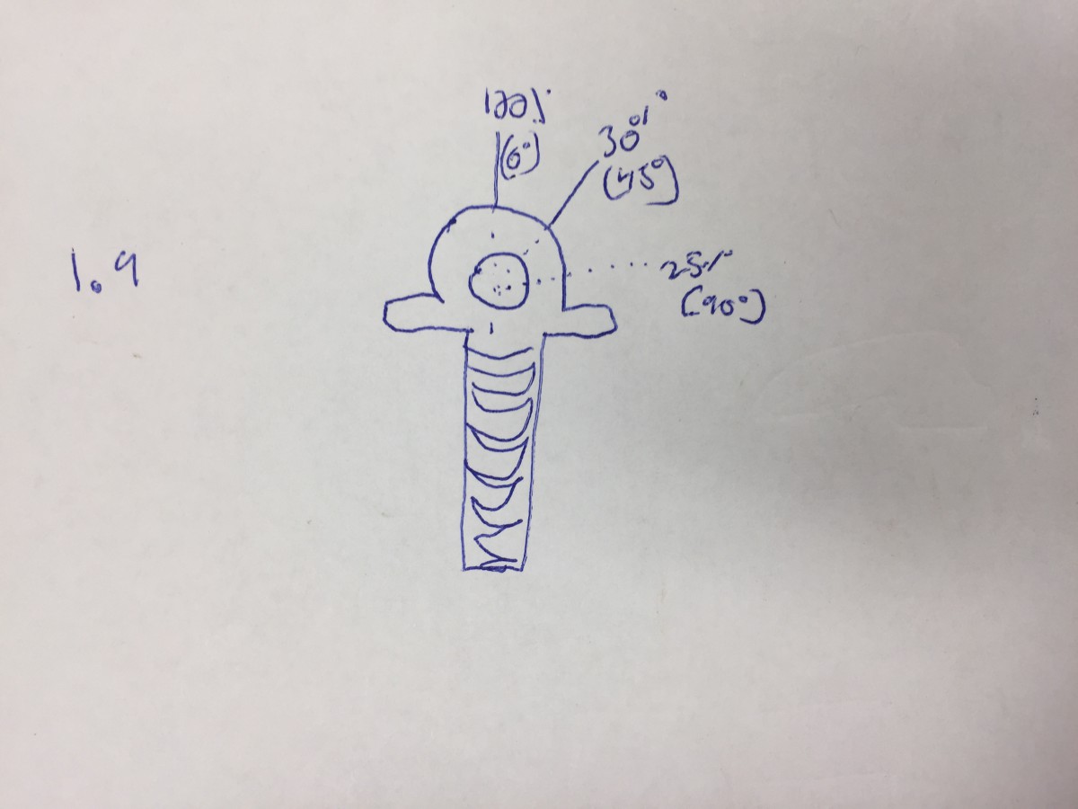
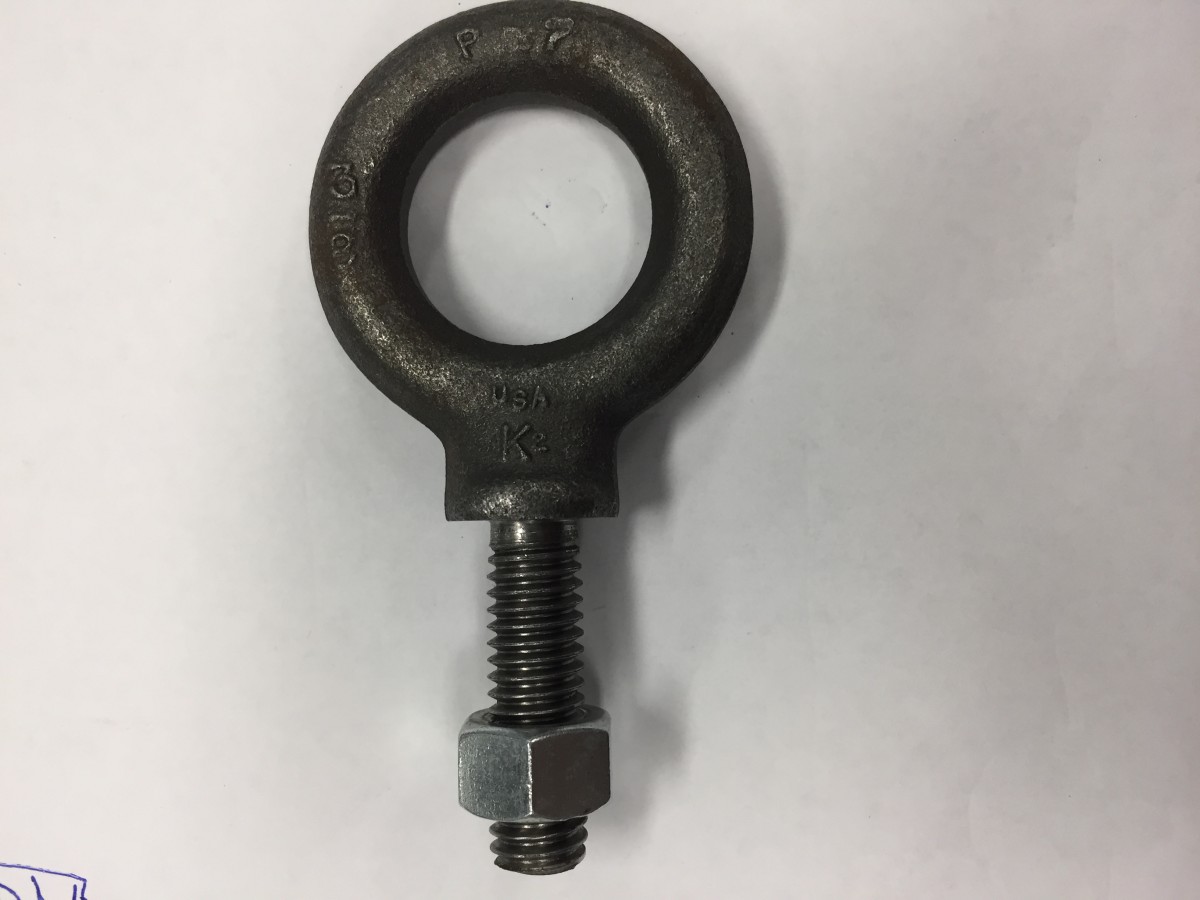
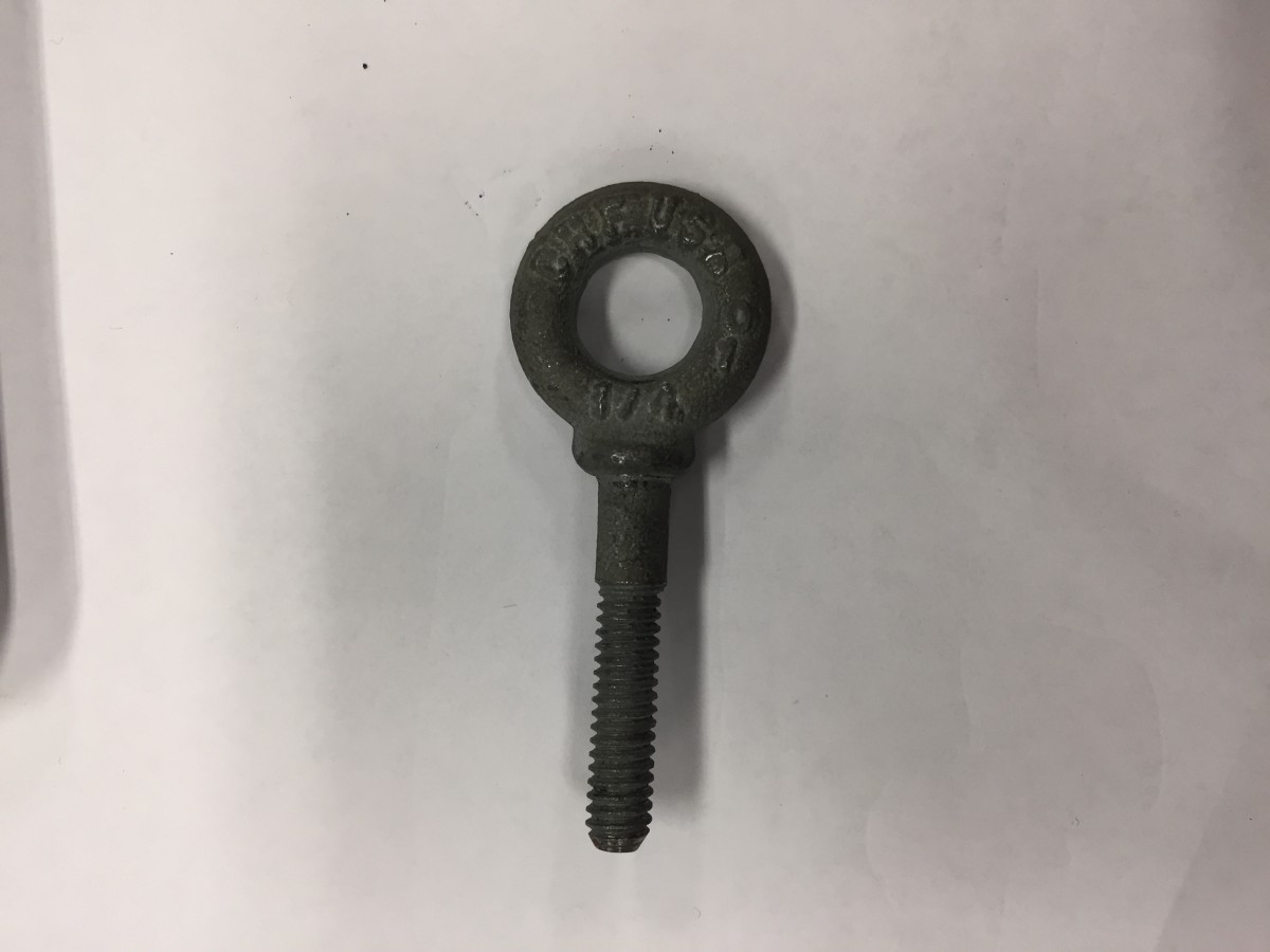
Eye Bolt: Shouldered forged eyebolt. *** Bent eye bolt is no good. Eye bolt is designed to be loaded directly in line (Figure 1.9) (Picture 1.8, 2.0)
Galvanized: Protects against rust
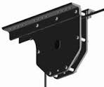
Things that attach to I-beam
Wide variety of I- beam clamp
Read Manufacture specs for size beam, weight, can it be loaded at angle, how to inspect and install.
Spanset, steel cable or piece of chain around beam
Things that attach to pipe:
Chain is handy since it is strong, cheap and flexible. Great as going around round objects. Can be both used as an anchor and adjustor.
Most common chain in theatre is grade 30 proof chain: lots of markings “not for overhead lifting” which has a different meaning for chain: use in hoist.
However most of the time we are using is to connect to a batten which is acceptable.
Not idea for going around corners.
Need to size chain and shackles so they fit together; may be overrated so the shackle will fit.
When attaching shackle to chain, ensure spare chain is free to move around
Another method is a batten clamp. Often you will find at permanent points.
Connectors
Screw pin anchor shackle, tighten to finger tightness. Should be marked with manufacture, country of origin, size, and WLL. Beware of cheap or knockoff shackles, ensure a manufacture is listed. Only buy rigging hardware from reputable dealers. Shackles can be loaded in line or slightly off axis. Many different shackles, for different uses. Screw pin is most common, since it is easy to install and uninstall. For long term use, must mouse the shackle, so it cannot rattle loose. Not good when loaded sideways, must be loaded in line. Other types included, just a pin, bolt and nut… different types have pros and cons for different uses.
Quick links, side screw: not great, very difficult to unscrew once loaded. John just doesn’t like them. Lower profile, could be useful, but rare.
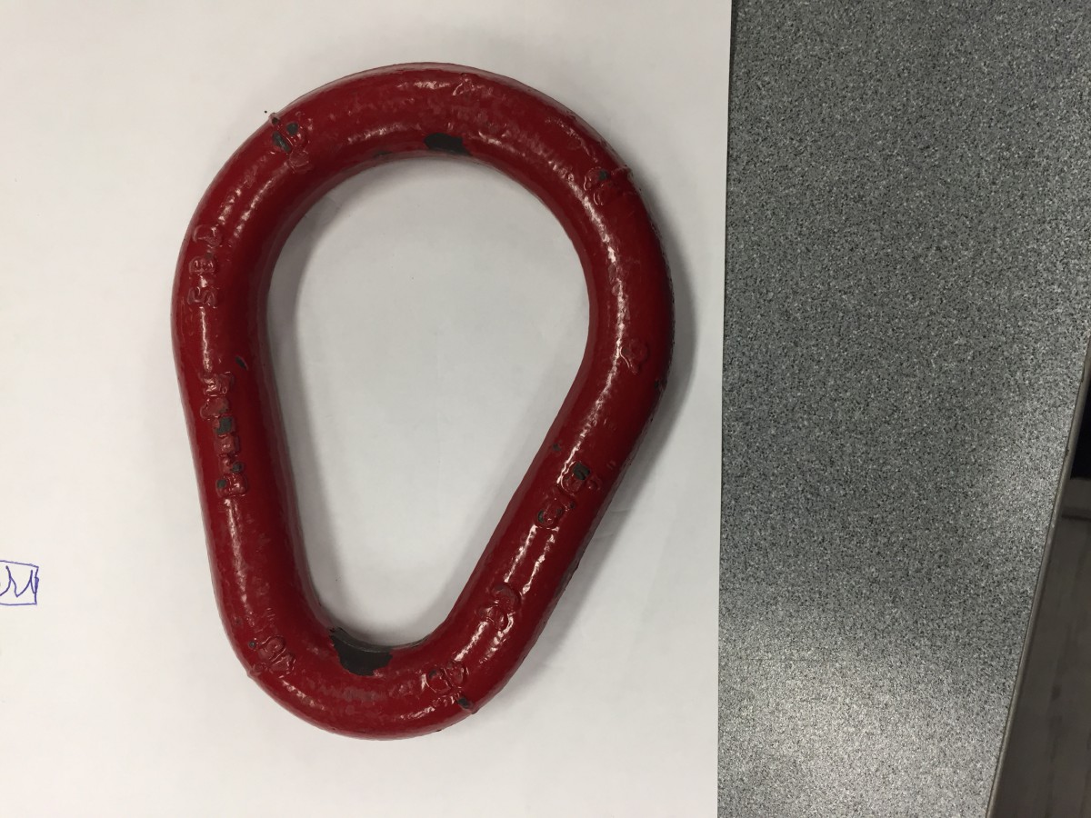
Pair ring: many different shaped of welded or forged rings. Useful in gathering many different points. (Picture 2.1)
“Acrobat Accident Story”: use correct hardware
Failure isn’t always immediate, just because it worked, doesn’t mean it always will.
Carabiner: only one load, in line
Adjustor
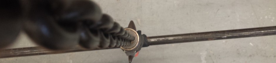
Turnbuckle- when turned they expand or retract; many different ends
Very handy, easily adjustable. If inline, adjustor could go anywhere, mechanically or strength wise. Placed so it can be adjusted easily. Mouse turnbuckles so they don’t move. Always have the same side up, so all turnbuckles are adjusted the same way
Look out: solid style, can’t see how much is left. Also avoid anything bent, must be forged. Very careful to not side load.
Batten Splices
Very often riggers will be responsible for replacing battens,
Schedule 40 pipe.
Sleeve to join pieces together. Plumbing fittings are not for rigging. Held together by hope. Different types of sleeves to connect pipe. Find something designed to be used for rigging
Wooden Batten clamp: Out of style
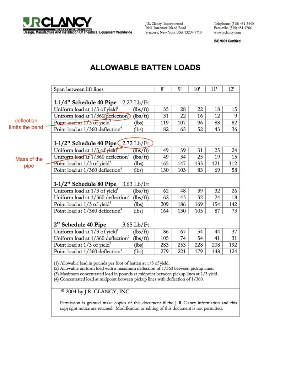
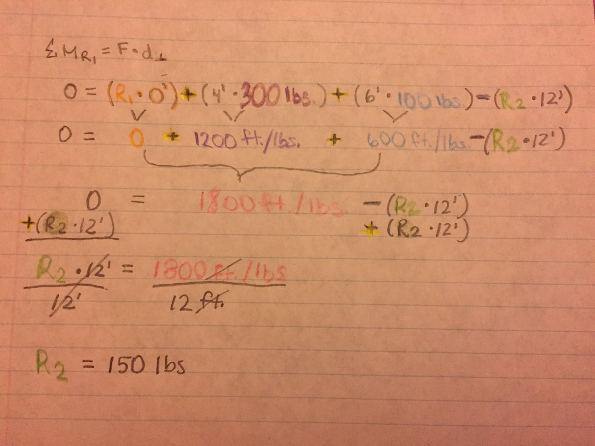
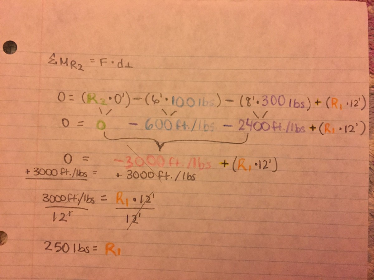
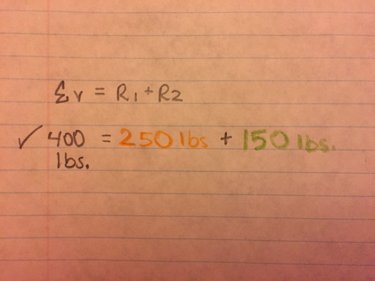
Choose tension member and calculating load. Must also choose all the other hardware. Start in Backstage handbook. Look up shackle WLL. Determine load on hanging point.
Rigging system is only as strong as weakest link.
Crosby Design factor 6:1
Tension Member might be weakest link.
Passed Out Hw 8 and Lab time to work on steel cable