Monthly Archives: March 2019

Lab experiments for now

This picture shows an example of a difficult situation to actually set up/slide gear wheels from different shafts to make the appropriate contact between one another

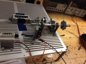
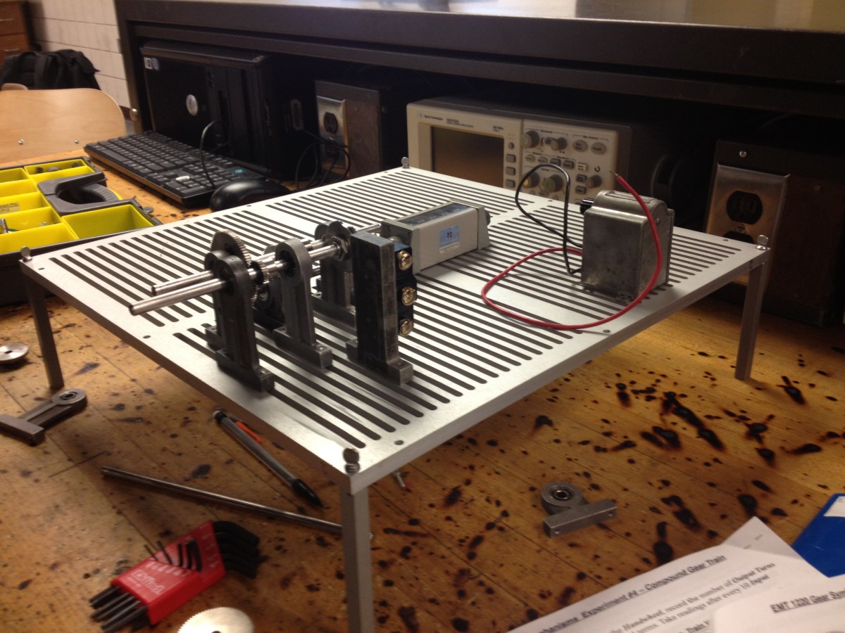
This sample above shows how it may not be recommended to set up gear wheel shafts with respect to the grooves/slots in the breadboard(note when shafts mounted on pillowblocks are parallel to the grooves, there is difficulty aligning different shafts across the “gap” space between the grooves; but if the shafts are at 90 degrees/perpendicular to the grooves then there are numerous ways to adjust the spacing from the pillowblocks sliding along the grooves to either move the shafts/gearwheels closer to other shafts/gearwheels or more distant

This picture shows better layout(can you see the difference in the orientation of shafts vs breadboard slots?)

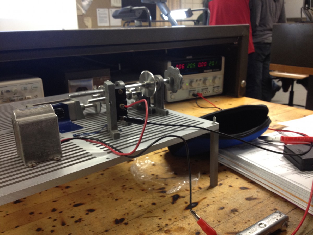
The picture just above these words shows shafts perpendicular to the breadboard slots/grooves so that there is easier adjustment between gearshafts spacing closer or farther (which is not depending on the standard “gap” of the breadboard as in the prior initial picture)


Lab experiments

sketchy sample sketch

Simple sketch for lab 7 (came out etchy) This just shows samples of a robotic arm

Just a lab 4 pic showing E/M counter vs mechanical counter

This sample picture just shows the elctromechanical counter on the bottom left and mechanical counter more towards top left

Problematic setup

As already mentioned in another post this sample picture shows mechanical setup where the shafts are parallel to breadboard slots(this can cause problems adjusting spacing between gear shafts; can you see why?)

Correct alignment of shafts with respect to breadboard slots is crucial here

Proper aligning of shafts relative to breadboard slots is key


Four-Bar Linkage Homework temp

This helps answer for a number of Test Questions

Basic Homework Question is related to this

The Bottom drawings show what we would like to obtain in sketch form for a homework question; prepare for the test by practicing

Four-Bar Linkage drawings of Extreme Left vs Extreme Right positions (top left sketch); showing scaling dimensions using centimeters rule(see two top right larger drawings of graph paper sketches) on ruler instead of inches

this temporary site location for hw practice for exam. Please try understanding AND answering BOTH computer-prepared printed sheets AND use my messy/sloppy graphing paper attempts on your own! Show me for some credit to test & use www.mekanizmalar.com/fourbar.html  as you were shown.. Do a search for Four Bar linkage on YouTube for ideas and helpful aids understanding certain basic principles like  https://www.youtube.com/results?search_query=four+bar+linkage

Some Internet Research topics of interest Some Internet Research topics of interest item options Hide Details

Useful videos to watch (if you haven’t already): How Watts Straight Line Motion mechanism works : https://www.youtube.com/watch?v=bsRmE5AU9x0

Chebyshev’s Straight Line Linkage: https://www.youtube.com/watch?v=ztMuScgSCHs

Kinetic art, Perpetual motion, Marble Machine: https://www.youtube.com/watch?v=ruiQR3CZE7k

7 Amazing Science Gadgets https://www.youtube.com/watch?v=wcKyq-e-Soo

Below is a sample link to a particular type of engines but look out for others on pumps, drives(like VFDs), motors (like brushless, stepper, servos), and applications for systems like incremental encoder, uchip on kickstarter, even just something that seems as simple as Hall sensors