Title: Making an arduino board using actuators, resistors and controllers. By connecting all the wires, and twisting the knob both clock and counterclockwise. 10/2/14 Started at 10:25am.
Objective: Making an arduino board using actuators, resistors and controllers. Making sure that the LED is functional and able to go from bright to dim when turning the knob. Andre’s task was to connect all the wires. Andrew’s task was to twist the knob the first time. And Matthew’s task was to twist the knob the second time around.
Materials:
- Arduino Board
- Potentiometer
- LED
- 220 ohm resistor
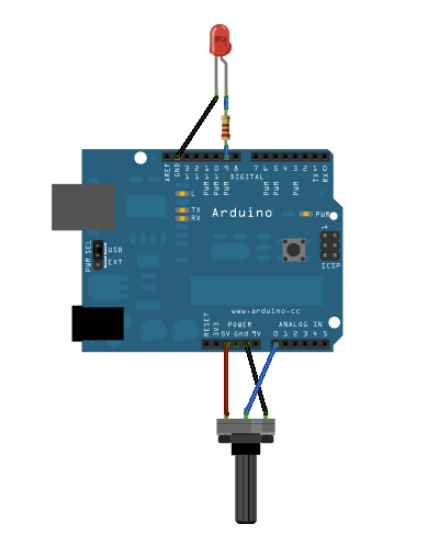
Methods: Andre connected one pin to 5v. The center pin to 0, and the last one to the ground. Andre connected resistor to pin 9. The long, anode of the LED should be connected to the output from the resistor, with the shorter, the cathode connected to ground. Andre ran into one issue which was not pushing the bulb all the way down, to get it working correctly. So we pushed the LED all the way down.
Results: Andre had set up the red and connected it to 5v. (power) Then connected the black wire to the ground. So when Andrew turned the knob clockwise the LED became more bright. When i turned it counterclockwise the LED became Dim, so the we achieved the first part of our objective. Then andrew switched the red wire to the ground port and the black wire to the power. And it succeeded because when matthew turned the knob clockwise and the LED became dim and when he turned it counterclockwise the LED became more bright.
Discussion: If our group were to continue we would connect the wires to different inputs on the board and see what would happen and then record the results. As long as nothing blows up along the way.
This the schematic for our project, that we got from the arduino website.