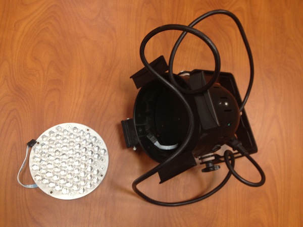
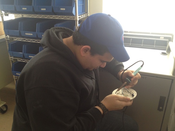
This week we’ve got a great enhancement for the project: John brought small LED lighting fixture and donated it to Hell Bunny. This fixture uses a whole bunch of red, green and blue super bright LEDs. They are three times bigger and much brighter than what we had before. Also, they fit almost exactly into the Rabbit’s eye sockets. I decided to use 2 red ones (one for each eye), and John hacked them from the lighting fixture (luckily for us, they were mounted on the PCB using through-hole method). John desoldered 7 or 8 LEDs, and we tested them – some were not working, others were working perfectly. However, their legs were very-very short, because they were trimmed during lighting fixture manufacturing process.
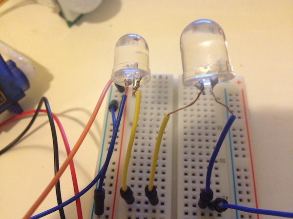
When I went home, I cut in half two jumpers, stripped their ends, and soldered them to the LEDs’ legs. Now we have much more flexibility.
After this was done, I went back to the code problems. Two of them were still unresolved:
- LEDs weren’t synchronized with the audio (they were ON all the time).
- Servo motors weren’t working with this code at all.
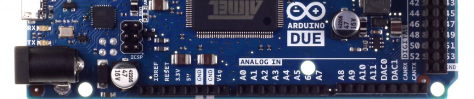
LEDs problem was solved very quickly after some research. I wired LEDs in series and assigned them to the Arduino digital pin 18 ( #define eyeleds 18;), which in reality is Analog pin 4. I don’t know exactly why, but now they are working together with the Wave shield.
Servo motors problem gave me a bit of a hard time. First, I was looking at some fancy sketches (with arrays and sophisticated functions for servos), and was trying to use a Copy-Paste technique to integrate them into my code, without complete understanding of what’s going on there. Of course, I was getting all kinds of errors, because if it doesn’t make sense to me, why would it make sense to the Arduino? So, when it became clear that copy-pasting is not a way to go, I decided to start servo motors part of the code from scratch.
First, I included ServoTimer2 library into the sketch (#include <ServoTimer2.h>;), then created two servo objects (ServoTimer2 theservo and theservo2). After this, in the setup section of the code, I assigned servos to pins 7 and 9 using the attach() method. Last step was to go to the loop section, find the ‘while (wave.isplaying) {‘ line and write the following after it:
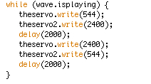
With Professor Baker’s help I found out that pulse widths in ServoTimer2 library are in microseconds, not degrees. With google I found out that default minimum is 544, max is 2400μs. I put this data in parentheses, then compiled the sketch and uploaded it to the Arduino, not believing that it would work. And to my great surprise, I’ve got this:
The entire circuit was working properly!!!!!
This being said, I hope the software part of our project is now done, and next week we will start working on the hardware. Also, next week I will solder the entire circuit in order to get the most reliable connection.

