Objective: use three potentiometers to individually control each of the primary colors of an RGB LED.
Materials:
Hardware: Arduino Uno, USB A/B cable, 1 RGB LED, 3 10K potentiometers, 3 220Ω resistors, breadboard, 8 jumper wires, wire strippers.
Software: Arduino IDE, Blink example from the Arduino IDE’s Examples folder, RGB LED Color Chooser example from the Arduino Playground.
Procedure:
- Connect Arduino Uno to the computer using USB A/B cable.
- Open Arduino IDE and configure the board and serial port properly.
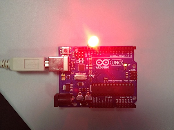
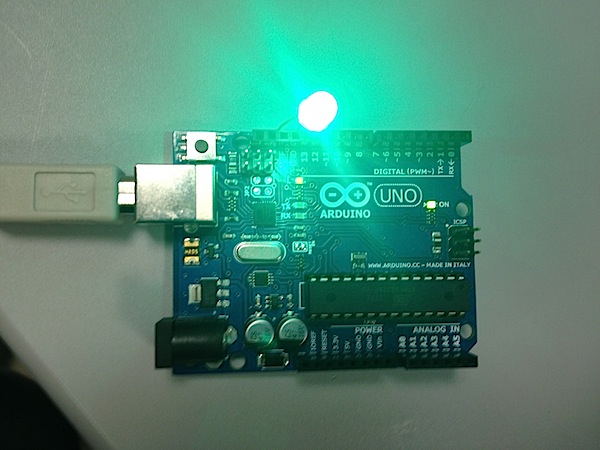
- Test the RGB LED by hooking up each of its legs (one at a time) to the digital pin 13 on the Arduino and running the Blink Example from the Arduino IDE. First we have to determine what kind of RGB LED is this – Common Anode or Common Cathode. If it is Common Anode, our LED should light up when its longest leg is inserted into the Arduino’s 5V pin, and one of the shorter legs is in the pin 13. Common Cathode means that in order to produce a light output the longest leg of the LED has to be connected to the Arduino’s ground pin. After having your LED up and running, test two remaining colors by inserting the shorter legs into the pin 13. Our LED gave us only red output, but no blue or green, which meant that two of the three channels where burned out. We had to replace the LED with another one and test it again. It’s interesting, but you can actually tell the difference between good and bad LEDs by simply looking at them: a good one’s head will be a lot more clear than that of a broken one. After testing our new LED,we’ve finally got everything on:
- Insert the LED into the breadboard, with Common Cathode leg going to the breadboard’s ground strip.
- Put 3 220Ω resistors in series with each of the three remaining legs of the LED.
- Hook up potentiometers to the breadboard: each black wire goes to the ground strip, each red wire goes to the power strip and each yellow wire (signal) goes to one of the LED’s legs.
- Connect the breadboard to the Arduino. First, use one jumper wire to go from the breadboard’s ground strip to Arduino’s ground pin. Then another jumper goes from the power strip to the Arduino’s 5 V pin. After this we had to connect two sets of three jumpers to the LED’s legs. According to the code, the first set of jumpers goes from resistors to analog inputs 0, 1 and 2, while the second set of jumpers goes from resistors to digital pins 9, 10 and 11. At the end of the procedure our wiring was looking like this:
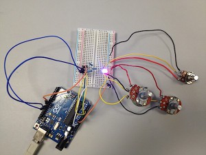
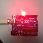
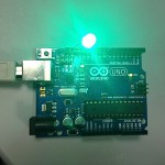
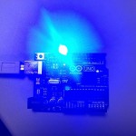
- Copy and Paste the RGB LED Color Chooser code from the Arduino Playground to the IDE, then compile and run it. If everything is right, you will be able to control each of the RGB LED’s colors individually.
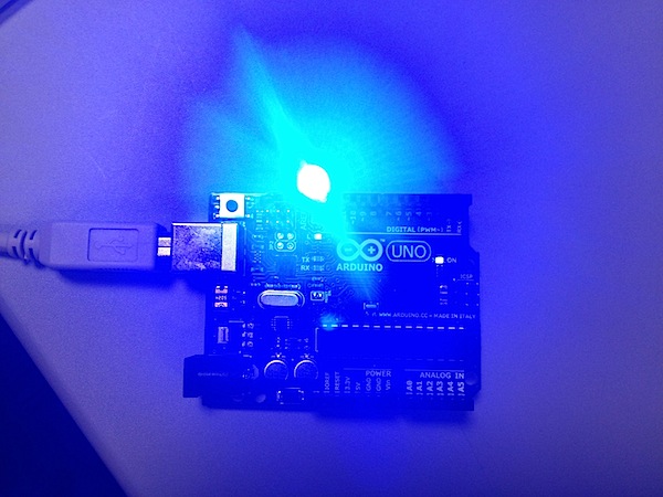
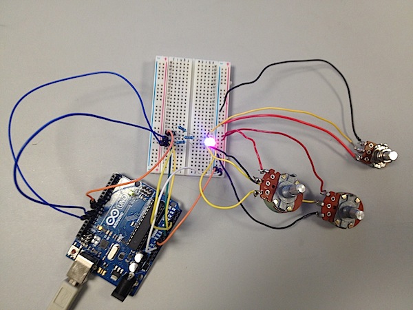
Results: we’ve encountered multiple problems during our procedure, starting with a broken LED at the beginning and ending up with the discovery of a broken resistor at the end. But all of the problems were resolved and finally we’ve got the following:

