Michael Sauder
Week 4 Lab Report
Objective: To disassemble a defunct network switch so we can view the interior components, with the goal of acquiring a sense of what components are used, how they interact, and how they’re assembled.
Materials: Linksys SRW 2008 MP 8-port gigabit switch, screwdrivers, prybar, camera.
Procedures:
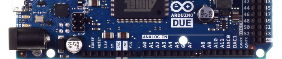
– Identify inputs/outputs
- 8 gigabit RJ-45 ports
- 1 9-pin serial port
- 2 SFP ports
- 1 48 Volt, 3.1 amp DC power input
- 1 PSU with standard power cord
– Disassembling of PSU (Power Supply Unit)
- Uncover 4 screws on bottom of PSU by prying off 4 rubber covers.
- Remove 4 screws using screwdriver. The screws are made of soft, easily strippable metal and did not come out easily – we successfully removed 3 of the screws and then used a prybar to crack open the case. A properly sized screwdriver with a larger handle may have done a better job.
- Remove 4 screws from bottom of circuit board
- Remove 2 screws from side metal shields
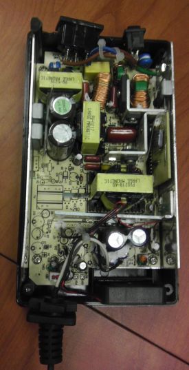
– Examination of PSU
- The PSU circuitry is mostly made up of capacitors and transformers. It uses thru-hole components, an older technology compared to modern day SMD (Surface Mount Devices). The circuit board was not completely occupied and had numerous markings and open spaces for additional components, indicating that the same circuit board is likely used for different devices or variations of the power supply.
– Disassembling of switch
- Using a large flathead screwdriver, pry apart the two black plastic covers, followed by the two metals halves – there are no screws.
- Unscrew 3 screws and 1 standoff on circuit board to remove main board from case.
- Unscrew 1 standoff to remove daughter board from main board.
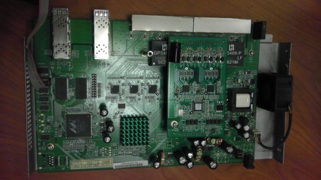
– Examination of switch
- The switch circuit boards were much more modern compared to the PSU, with a variety of microprocessors and SMDs, and few if any thru-hole components. Being newer, the components are smaller. But the switch is doing much more than a simple power supply, so there is a significantly larger number of components.
Results:
After some initial struggle disassembling the PSU, we were able to see both the PSU and switch circuit boards and the components on them, and Professor Baker was able to explain what some of the various components do and how the units were assembled.

