Objective: To add a sensor (potentiometer) to our basic Arduino setup, troubleshoot, and make a few basic changes.
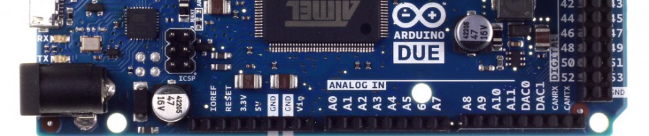
Materials: Arduino Milanove (controller), Potentiometer (sensor), cable connector, LED (actuator)
Procedure:
1. Plug the arduino into the computer by using the USB port. (check to make sure the power light is on and that the LED on the board is blinking. If all is well so far attach LED to port three.
2. The next thing to do is to make sure that the connection to the computer is working properly. This is done by:
*making sure you have the correct board and port connection
*you then must upload a program and test compile it.
*then make a change to the program and recompile and rerun it.
Once this is done and has executed successfully you are finished troubleshooting and can start the actual lab.
3. Open and upload the Analog Read Signal from the public domain sample codes. Compile and run.
Changing the dial changes the output.
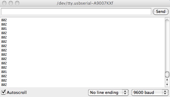
This is because it is a digital 10 bit representation of the data, and by explaining this you can impress 7-10 year old boys. Please note that the light on the board reads “on because it is flashing at 9600 bits per second. ) (please note this must be initiated from a specific analog port.
What happens if y0u take the delay out? We commented it out to see. Surprisingly nothing bad happened. By increasing the delay it causes the display to print out the sample reading at a much slower rate.
*The sample rate needs to be twice as fast at minimum of the thing you are sampling – this is called the Nyquist Shannon Frequency theory. This is true of just about anything, film, etc. audio should be twice what a human ear can pick up plus an additional 10% for good measure.
If you change the pin then the led should be controlled by the sensor. It was important to change it pin 11 and in the code, remembering to re-compile
Results:
The end result of the Analog Read Signal program is to see an output of numbers in the usb serial window. In the case of the one we worked on the maximum number was 1023. This number was reached more or less quickly by turning the dial on the sensor up or down. This proves that the program is successful. Our delay changes resulted in changes in the display speed as well – so this portion of the experiment was successful as well. Once we made changes in the pin and output we were able to use the sensor as a dimmer. Therefore all portions of today’s assignment were successful.

