Overview
Interior space is the resultant of a structural system that provides an armature for the envelope and finishes that surround and define the edges of space, including the floor below our feet, the ceiling over our head, and the walls rising around us.
Interior space requires span, the distance from one side of the space to the other. A structural element must be designed to safely achieve the spanning distance to support itself as well as any other loads that may act on it. The selection of a structural element is a process of assessing the pros and cons of all the possible options, which are rooted in the materials available, their properties, and the size and shape each material is fabricated into so it can serve as a functional structural element.
This assignment combines the development of a three dimensional representation of the selected floor(s) of the case study building and the application of a system(s) of structure to span across one or more spaces making a deck for a roof or a floor above the space. Each structural element will be sized using simple rules of thumb. The full system will be documented as an axon and a section view of each element of the system. All elements are to be dimensioned, labeled, and annotated with details including the span dimension and the rule of thumb applied as well as the reference for the rule of thumb.
Assignment Model/Video Demo: https://www.dropbox.com/s/0wka6cpl1tgsdg9/Federal%20Hall%20Structure_axon_sections.mp4?dl=0
Assignment Context:
This assignment is focused on applying the reading material to help build a deeper understanding and direct experience of the concepts discussed in the text.
Prerequisites:
Understanding of three-dimensional projection, completion of the required readings.
Recommended Text:
Ching, Francis. Architecture Graphics. John Wiley and Sons, 2009.
Plagiarism:
Student work submitted must be original and developed individually. Tracing is not acceptable. All construction lines and notations during drawing construction are to remain visible at final submission. Drawings without construction lines (guidelines) will be downgrading significantly.
Due Date(s)
6pm day on assigned due day (see Schedule)
Learning Outcomes
| Learning Outcomes | Assessment Methods |
| Upon successful completion of this assignment the student shall be able to: | To evaluate the students’ achievement of the learning objectives, the professor will do the following: |
| Develop coordinated, accurate, and consistent axonometric views demonstrating the proper use of axon drawing conventions. | Review student case study floor plans for accuracy, coordination, and consistency as well as the application of line weight and drawing conventions following assignment rubric. |
| Apply Information from the reading within the discipline. | Review student applications of disciplinary concepts in drawing assignments. |
| Understand and apply basic principles of structural characteristics of materials following rules of thumb. | Review student drawing assignments for accurate application of rules of thumb to sizing structural elements for a specific span. |
Instructions
NOTE: All drawings to be on 12″x 18″ sheets at scale listed below unless otherwise agreed with Professor Montgomery
Final Deliverables:
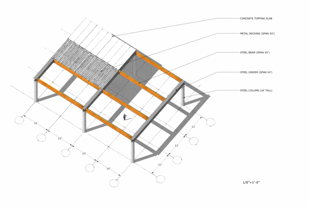
- Structural Bay Axon @ 1/8″=1′-0″
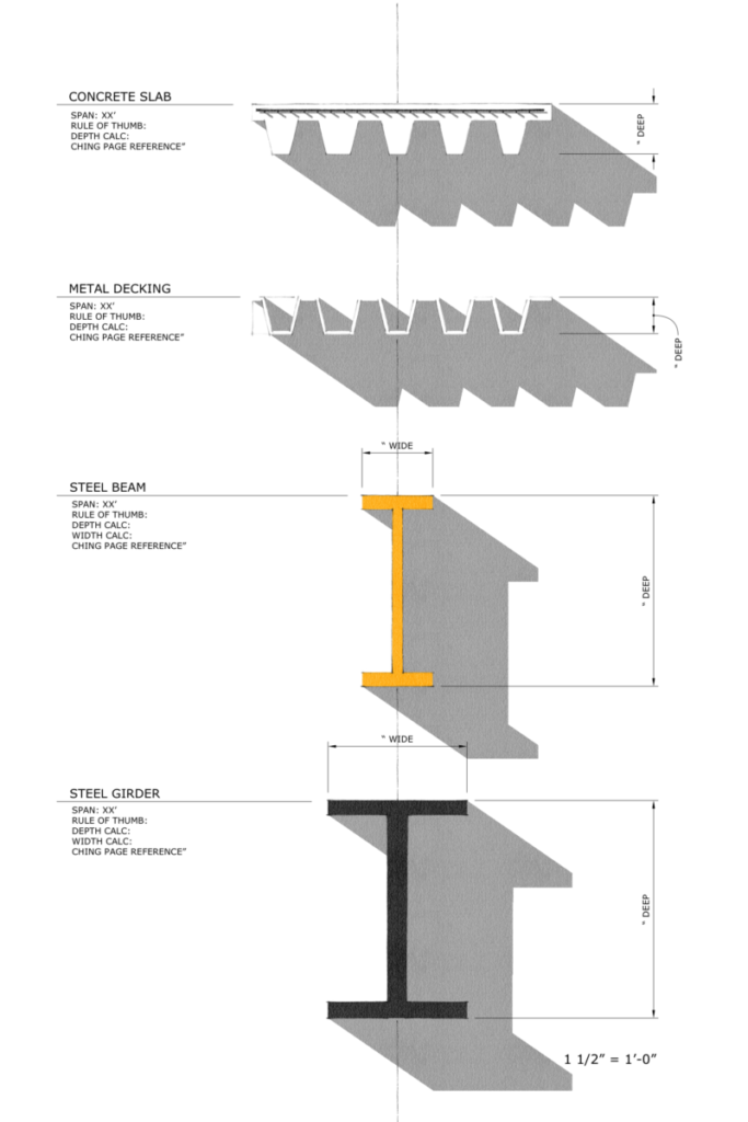
- Component Sections @ 1 1/2″=1′-0″
- Calculations and Annotations (Lettering to be 1/8″ high max)
Follow these steps:
- Sketch various configurations for the structural system
- Select one configuration and work through the calculations using rules of thumb for each layer and component
- Sketch each component in section and mark dimensions of depth and width
- Layout out reference lines for axon detail (structural grid lines and primary guide lines)
- Using guidelines, indicate vertical structural elements (15′ tall, 18″ square or diameter)
- Working in the sequence of construction, layout each layer of elements using peel away strategy to show clearly each layer (see mockup above)
- Finally axon line weights and annotate each component in system.
- On second sheet, draw center line for component sections
- Using guidelines, layout each component section at required scale, started with the primary beams 1″ above the bottom of the sheet.
- Add dimension strings to each component to indicate depth and width. See guide for dimensions here and for lettering here
- Using 1/8″ lettering, with space between each line, show all steps of structural calculations, including page reference for Ching’s rules of thumb.
- Complete each of these drawings. Scan on flatbed scanner and format per the course formatting guidelines (found here)
- Submit all formatted files to the dropbox folder found here
Grading Rubric
| ApproachingBenchmark | Benchmark | Approaching Capstone | Capstone | |
| Lineweight Distinguishing elements especially cut lines (poche), grid lines, transparent elements, finishes | Lines are consistent thickness and quality, in the correct alignment | In addition, two line weights are distinguishable, including cut line | In addition, three or more line weights are distinguishable, including some finish textures | In addition, transparency is clear, centerlines, grid lines, dimension lines are shown w/ correct line type and line weight. |
| Drawing Organization and Accuracy Elements are shown in the correct relationship to reference lines and each other | Structural Grid is established | In addition, structural grid is dimensioned accurately and labeled correctly | In addition, major elements are accurately placed in relation to the structural grid | In addition, all elements are carefully located in relationship to each other |
| Construction / Guidelines Guidelines and constructions were utilized in the careful construction of each drawing | Guidelines are used for overall layout of drawings | In addition, guidelines indicate orthographic projection axon construction. | In addition, guidelines indicate geometric relationship between the elements | In addition, guidelines are used to construct the detailed of each element in axon and section. |
| Structural System The structural system of the is clearly understood. | General configuration of structure is depicted | In addition, relationships and alignment of the structural system are accurate | In addition, each element has the correct general profile and section | In addition, each section is accurately dimensioned and sized per calculations |
| Axon The key elements of the building are articulated and projected in three-dimensions | Key elements are shown in three dimensions. | In addition, 3-d projection is accurate and coordinated w/ plan | In addition, each layer of the structural system is depicted | In addition, relationship of each layer is accurately positioned and clearly communicates system |
| Calcs The structural system is properly calculated utilizing the details and rules of thumb in the required textbook reading. | Spans are accurately measured and understood | In addition, rule of thumb is identified and documented and referenced to textbook | In addition, calculation is accurately executed and documented | In addition, structural element’s dimensions follow accurately results of calculations |
Resources
- Module 3 Sketchup Support Videos: https://openlab.citytech.cuny.edu/arch1231/module-3-assignment-resources/
- For some refresher resources on drawing plans, sections, and elevations, see this link: https://openlab.citytech.cuny.edu/arch1231/drafting-support-resources/


Leave a Reply