Category Archives: models

Journal 11/11/2015 presentation model

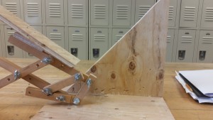
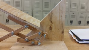
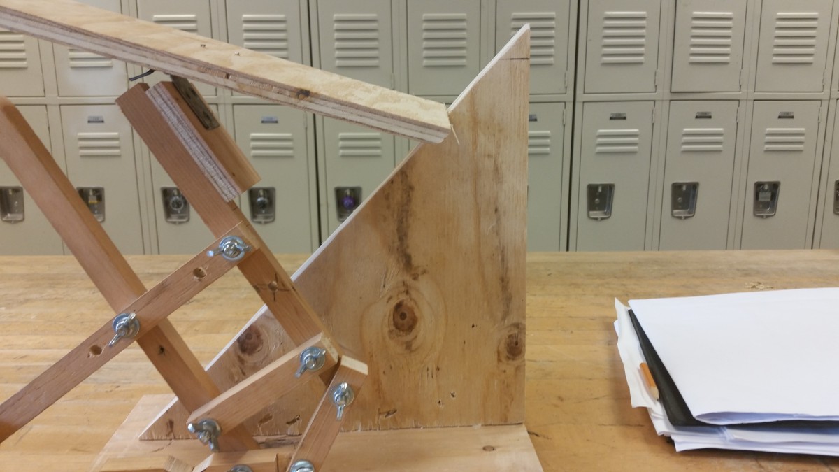
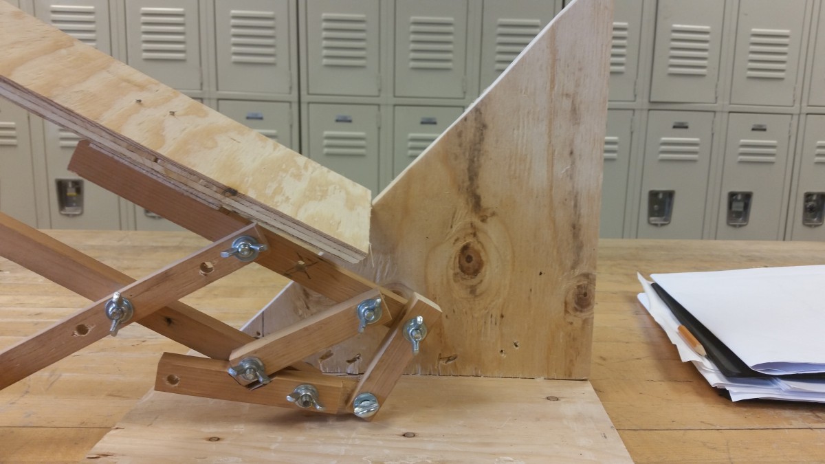
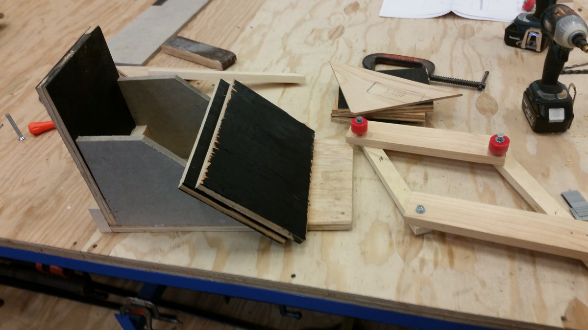
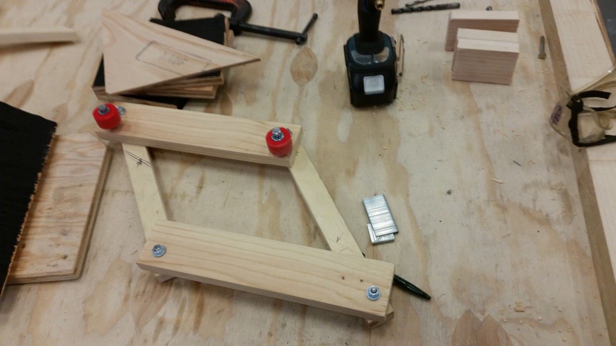
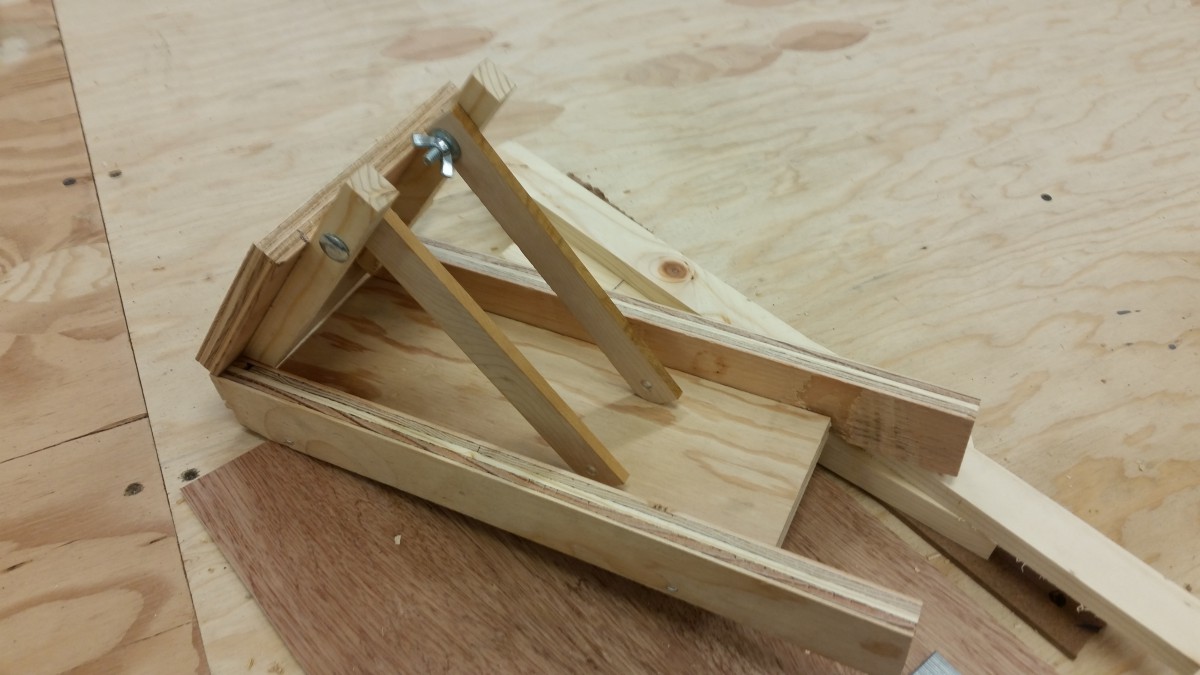
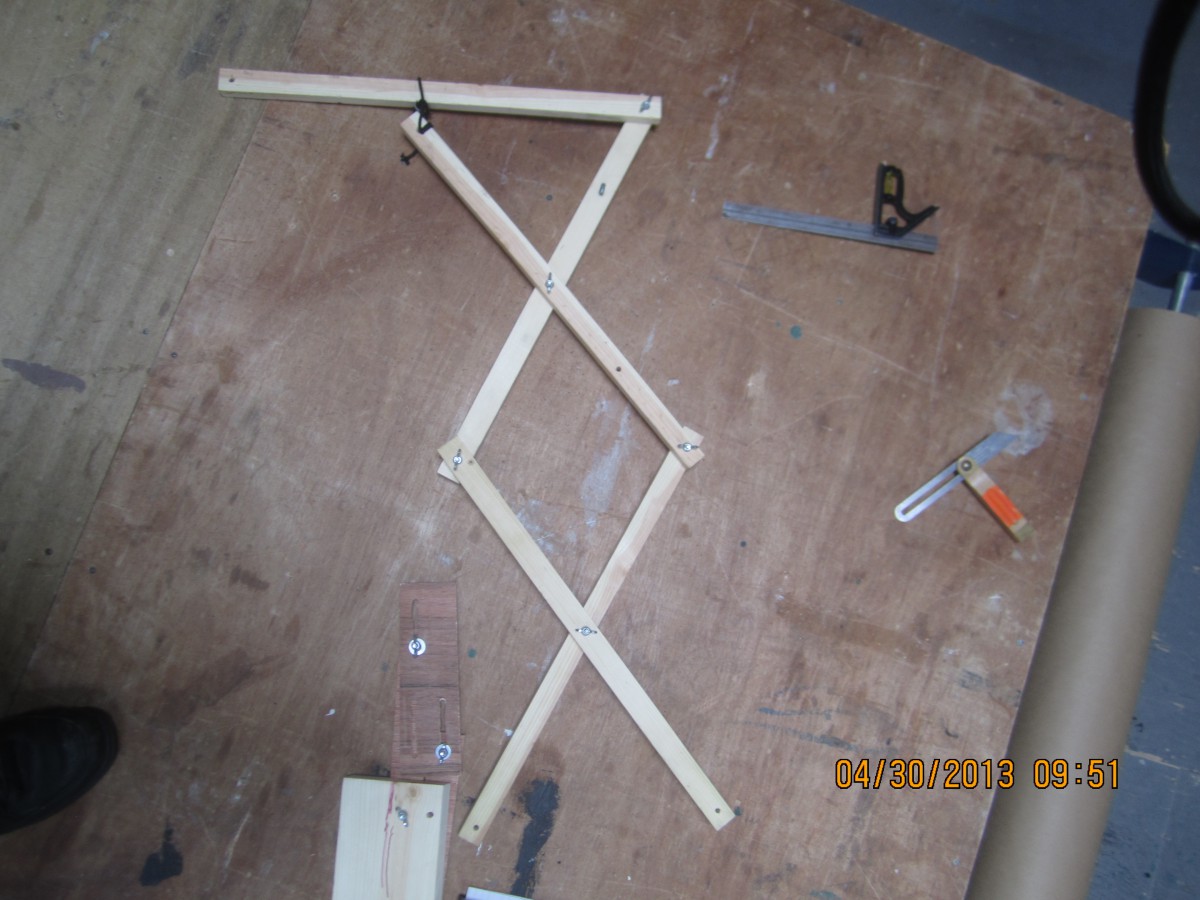
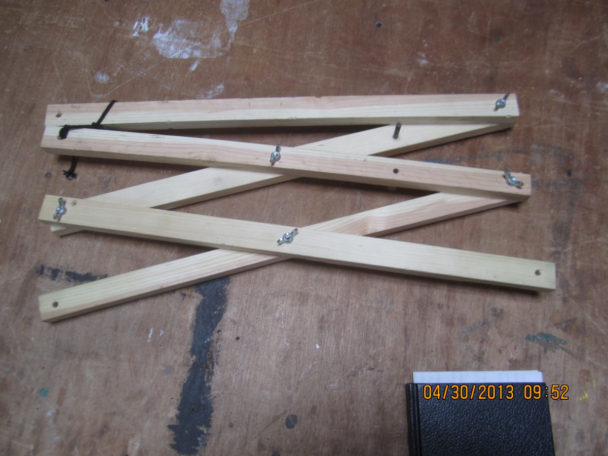
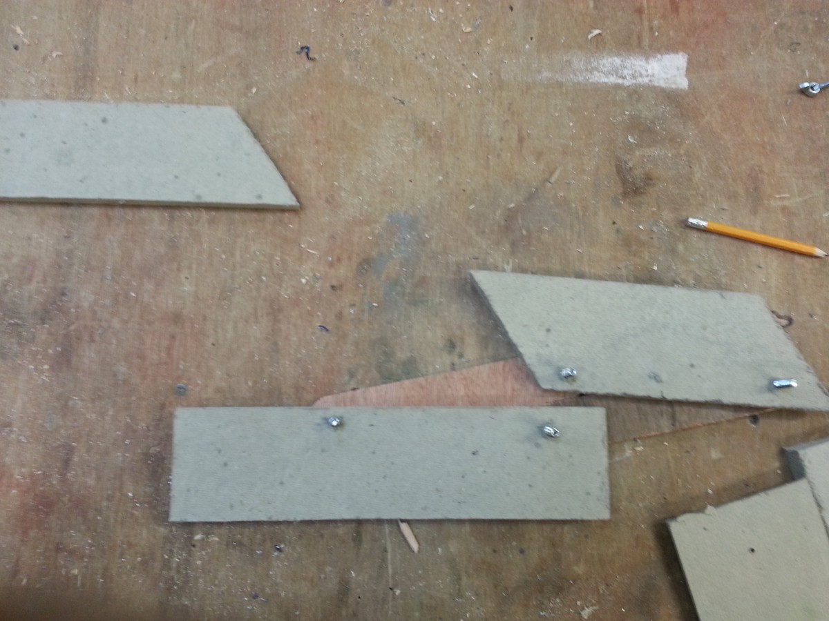
I completed the proof of concept and I have constructed a cleaner model for presentation purposes.

Capture cutlist pic

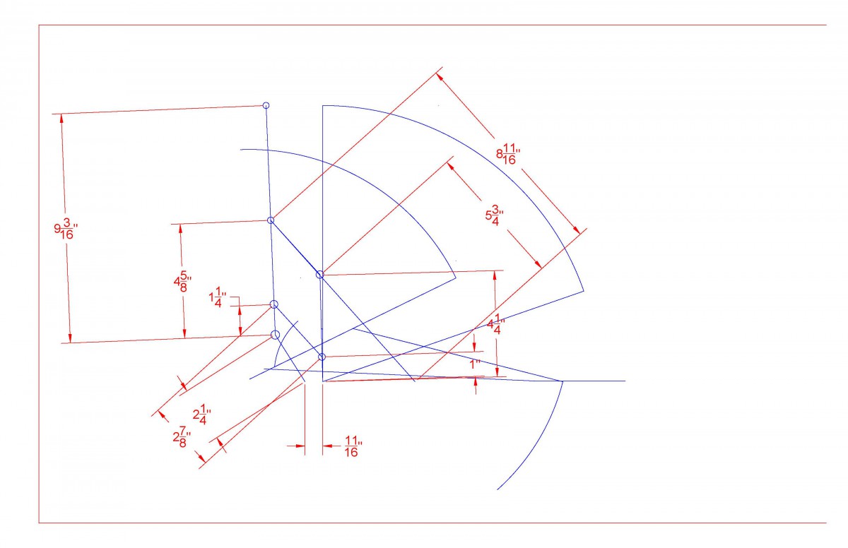
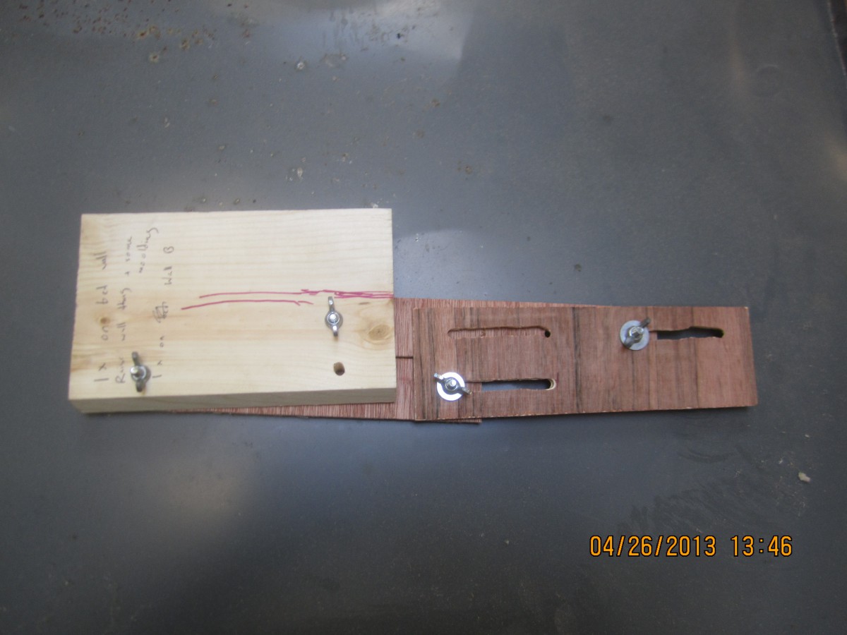
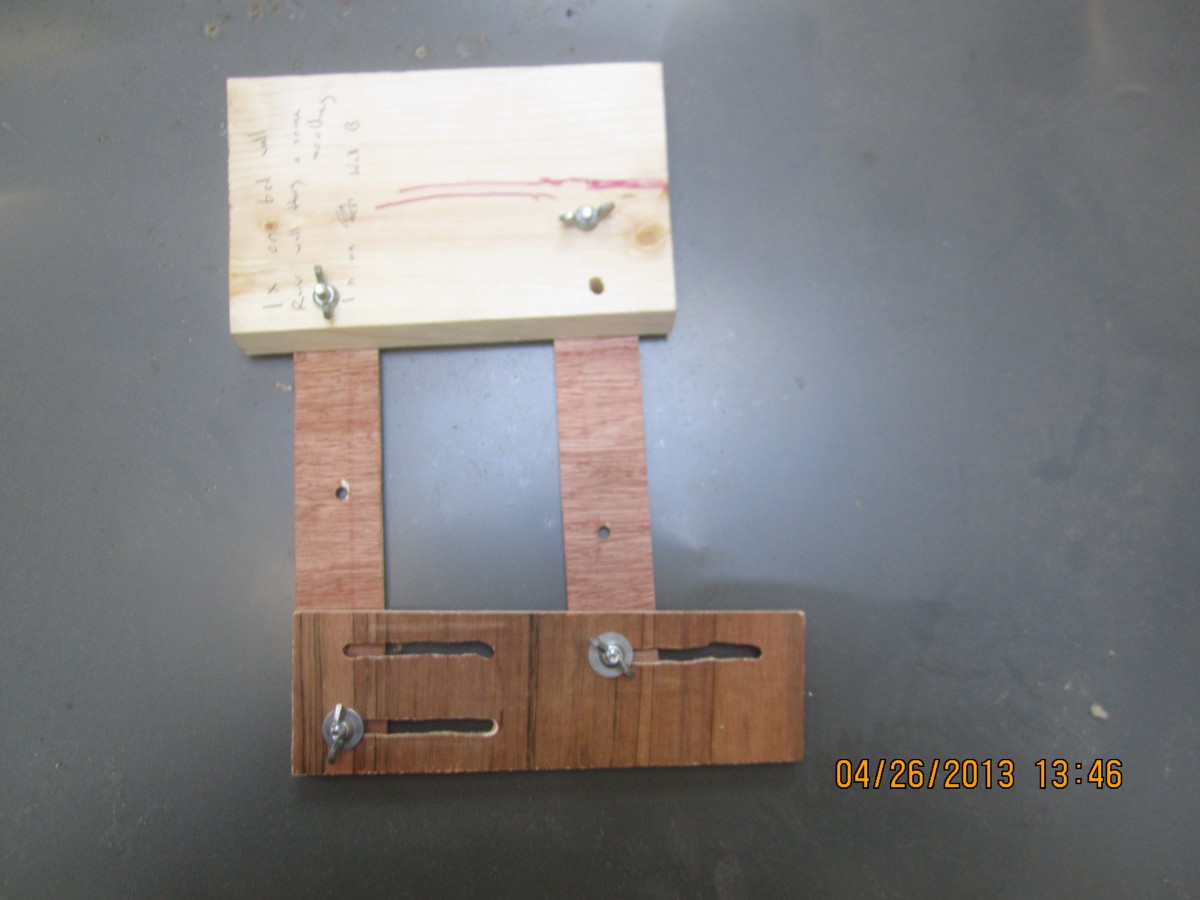
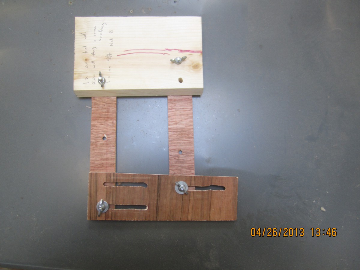
The unevenness of lumber is still an issue that caused the track to get narrower towards the back of the track and minor modifications were needed to get the model to work consistently. The legs should be offset from the edge enough to account for the most extreme angles of the transition.

20151124_152106

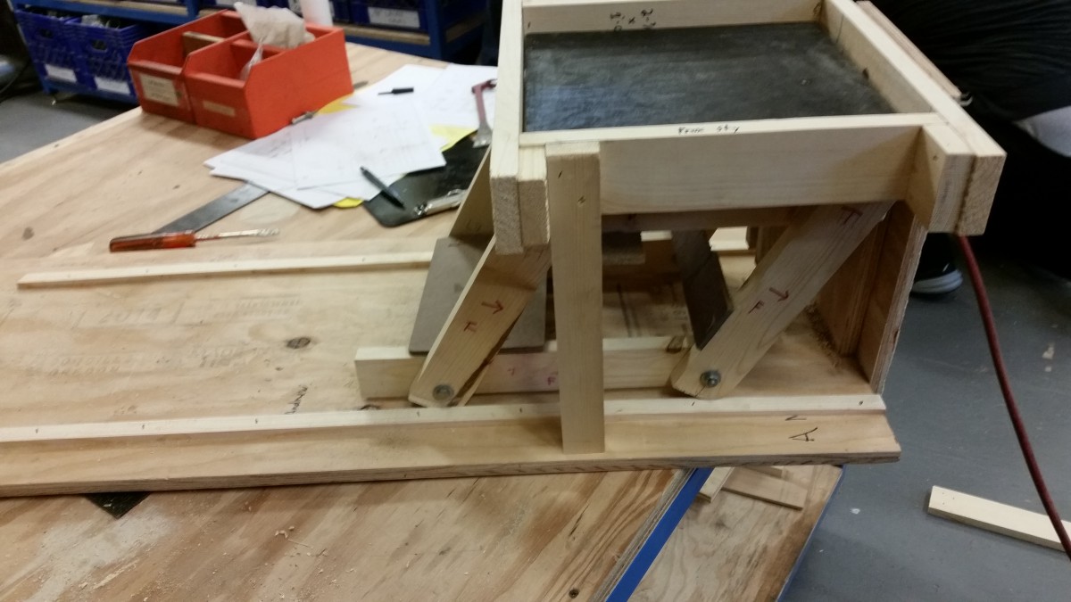
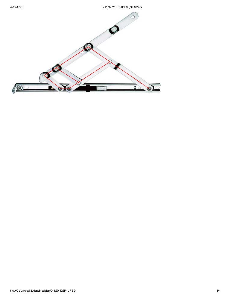
In the future I will try a using an absolute  reference point to minimize the impact of the cumulative inaccuracies in relative measurements

20151124_160345

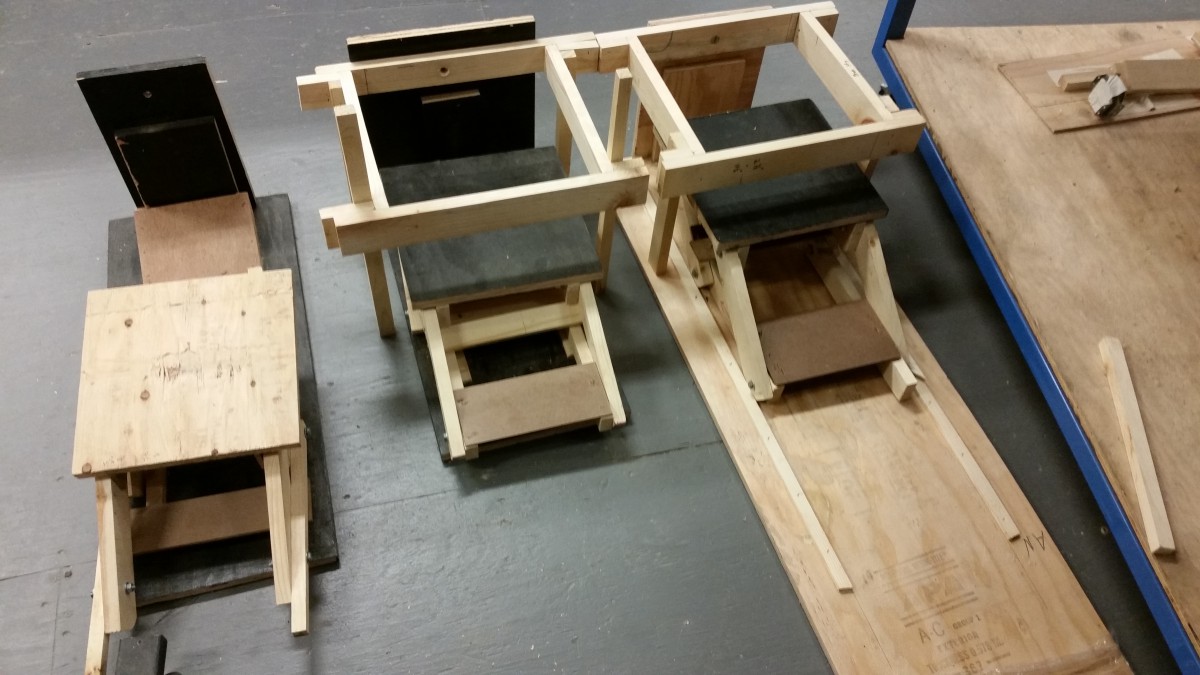
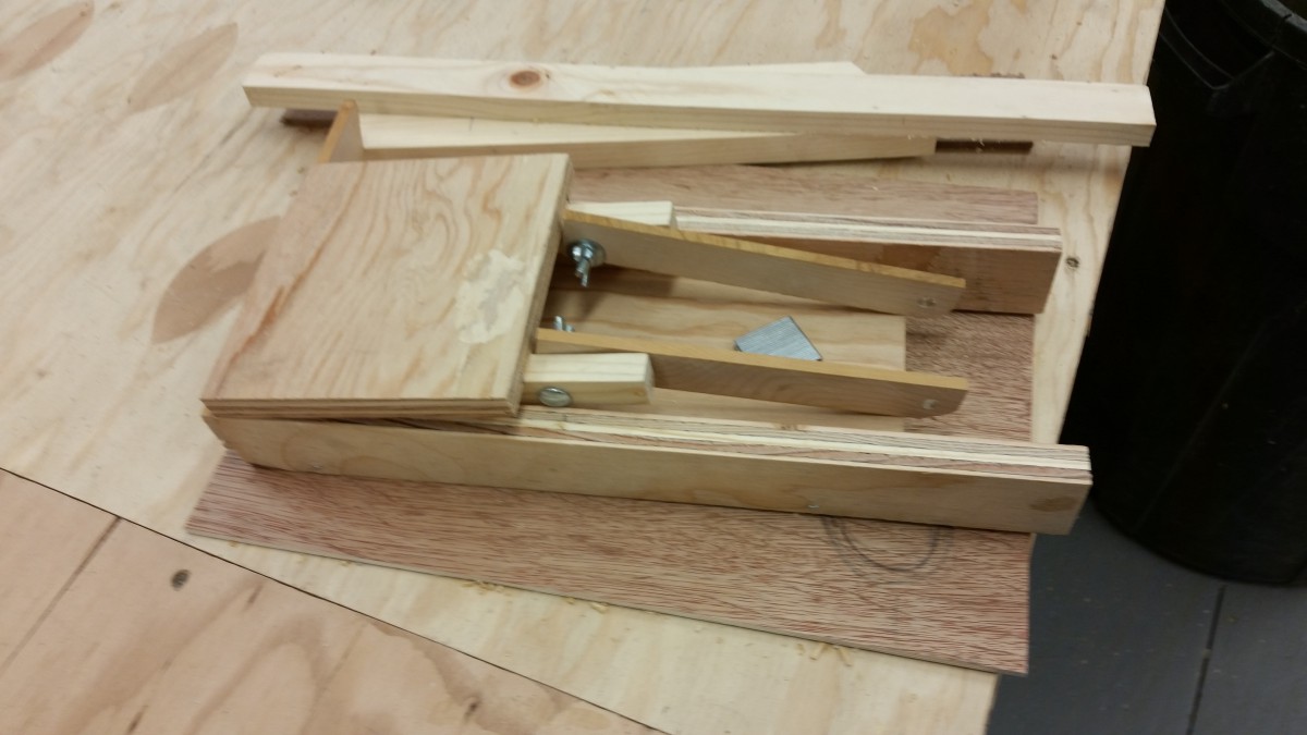
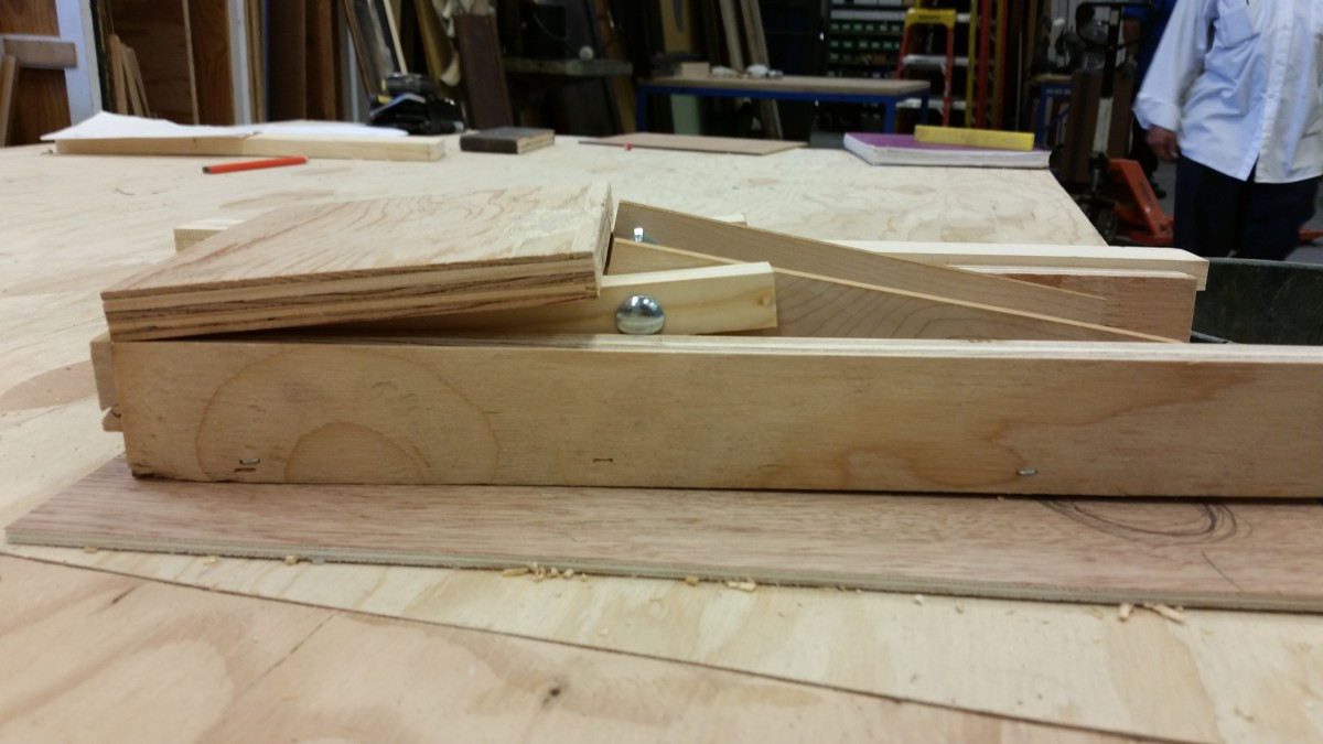
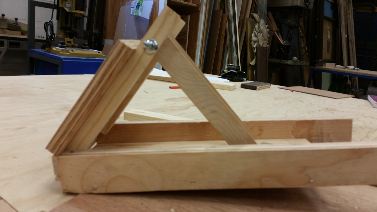
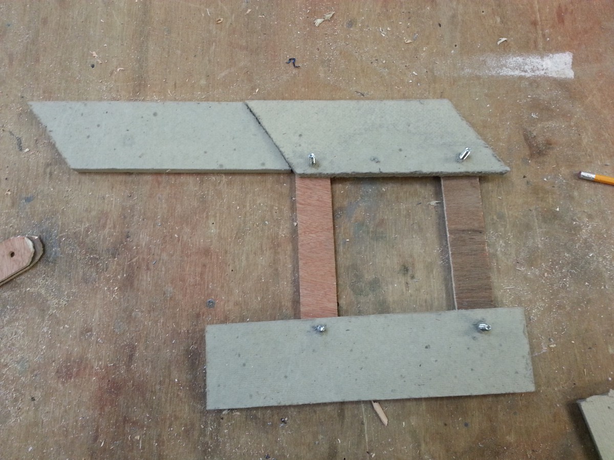
Starting from the left model: prototype, proof of concept, and the presentation model.


journal 10-28-2015 track and model

I finished a track and ramp for my model. The mock up the stud wall and triskets deck that simulates the parameters in the Voorhees theater floor. The ramp and track are fixed relative to the opening in the deck. The track has some rough corners that bind the platform but should be fixed with some smoothing.

I have moved the track wheels from the edges of the platform to the base of a center leg positioned in the middle, much like an R2D2 leg. This improved stability by supporting the center of gravity and use a ground level ramp instead of ones that would have to be suspended.

This design version does remove the redundant support from the track and wheels and rest the load solely on the legs of the platform.

Because of the sharp angle of the ramp, the track causes the platform to lift off of its front wheels before the legs begin to elevate the platform that could pose an issue binding with the deck.

I would want to see if a shallower ramp with a smaller angle or a smaller center leg could give me more room to clear thicker deck material for more structural integrity.


Journal entry 10/8/2015 Drafting

I worked in autoCAD to revise and model a new arm for the platform. I ran into autoCAD’s limitation in making moving model and had to map out the positions of the arms for each frame of movement. I used 3 frames and mapped an arc to determine the path of the trapdoor through the deck to estimate how much clearance each design would need.

Since the travel of the platform is a swinging arc, I would need a need to have a mitered edge or a method to swivel the deck out of the way so the trapdoor can shift into place without compromising the strength of the deck.

Journal 10/14/2015 prototyping

I used the 4 steel bar sliding hinge to draft a model that would lift and support a platform on a ramp.

20151015_135906

In AutoCAD, I had trouble defining the limitations of movement a multi-axis arm would have. In a meeting with my adviser, I learned that such properties and constrained can be designed in AutoCAD Inventor but learning an entirely new CAD program would be outside of the scope of my project, but it would still be interesting to learn.

20151009_14031720151009_140309  20151009_14024020151009_140214

The track had too much friction to function like I imagined it and it failed to move the platform into position without more points of constraint. What it did accomplish was creating a leg for vertical compression that would at least ensure that the platform rested in a fail safe arrangement should the pneumatic lose pressure.


20151015_135853 20151015_135858

The new track and platform builds upon the vertical legs and angled track design. The track has 2 parts, an incline that raises the platform just under the deck and a vertical lift that moves the platform to the level of the deck and places the arms into vertical compression.

I would like to have the arms set in such a way that it would lift the truck of the platform off of the bottom track when the arms swing into vertical, kind of like stilts.

Journal 9/27/2015 reverse engineering


The important parts of the sliding hinge are its points of articulation.

I used a PDF image to trace over a stock image of a hinge then I reference the drawing into autoCAD and made some measurements  to base a prototype off of.

Sliding Hinge PDF

I found it difficult to map the arcs of multiple axises as all the joints move relative to one another.

Ang Trapdoor10-02-15-Sliding Hinge

By using circles and arcs I as able to map where joints would be and should move.


Journal 9/18 test model

This is a model based on the sunroof cassette. The end of the track is level with the stage deck while the other end is lifted up with a set of levers.

Like the patents, this design uses the the same force that moves it forward to prop the arms up and change the angel  of the platform when it reaches the end of its track.

I still want to find a way to have a physical lock that can be done and undone by the same cylinder that move the platform. I want to have a structure that can remain safe should the pneumatic or hydraulic cylinder loses pressure.

20150917_12571920150917_125709  20150917_125726 20150917_125756 20150917_125805