Met with John to discus the proof of concept model and preperations that needed to be made for the presentation model.
Met with John to discus the proof of concept model and preperations that needed to be made for the presentation model.
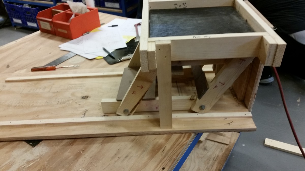
I completed the proof of concept and I have constructed a cleaner model for presentation purposes.
The unevenness of lumber is still an issue that caused the track to get narrower towards the back of the track and minor modifications were needed to get the model to work consistently. The legs should be offset from the edge enough to account for the most extreme angles of the transition.
In the future I will try a using an absolute reference point to minimize the impact of the cumulative inaccuracies in relative measurements
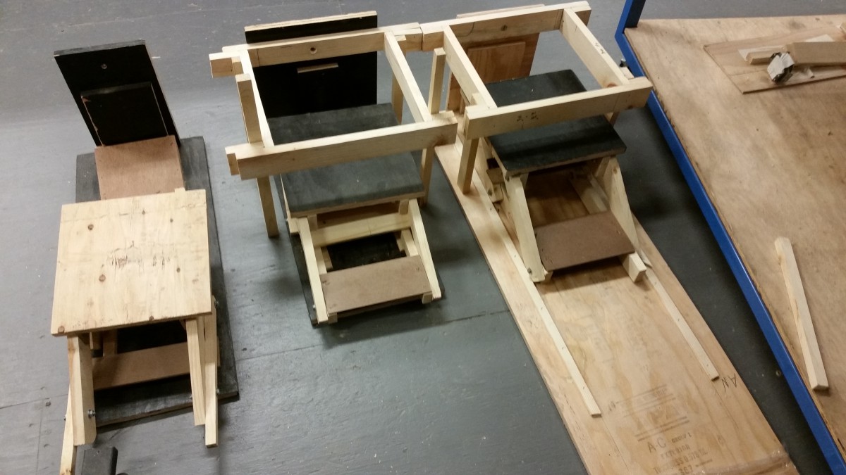
Starting from the left model: prototype, proof of concept, and the presentation model.
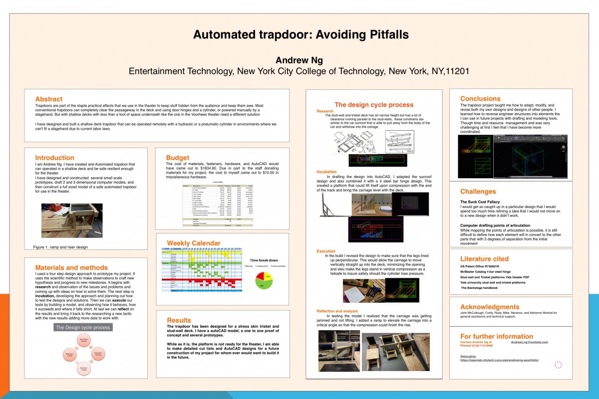
Due to file size limits, the poster can only be uploaded as a jpeg for now.
This week has been all about paper work, documentation and presentation.
I hope to be able to post the full powerpoint too.
Completed a 1 to 1 scale model that has meet my goal for movement and stability. I will adjust the lengths of the legs to account for the thickness of the plywood. I need to lengthen the track so that the truck I plan on constructing a model for presentation. while I was not able to construct a full trapdoor for the theater, I can make design a CAD files and shop orders for a future build of this project, if someone wants to take up my project.
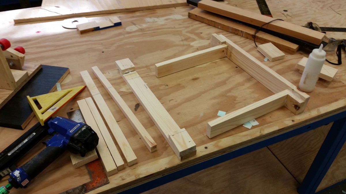
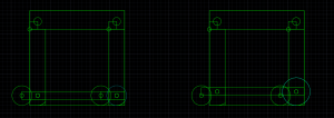
This is the frame to stand in for the thickness of the platform
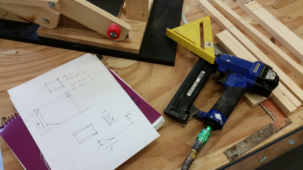
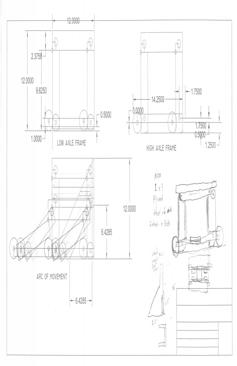
CAD Designs and notes while building.
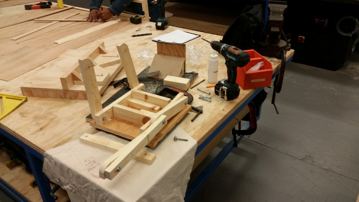
Squaring up the frame is important for symmetrical movement in the legs.
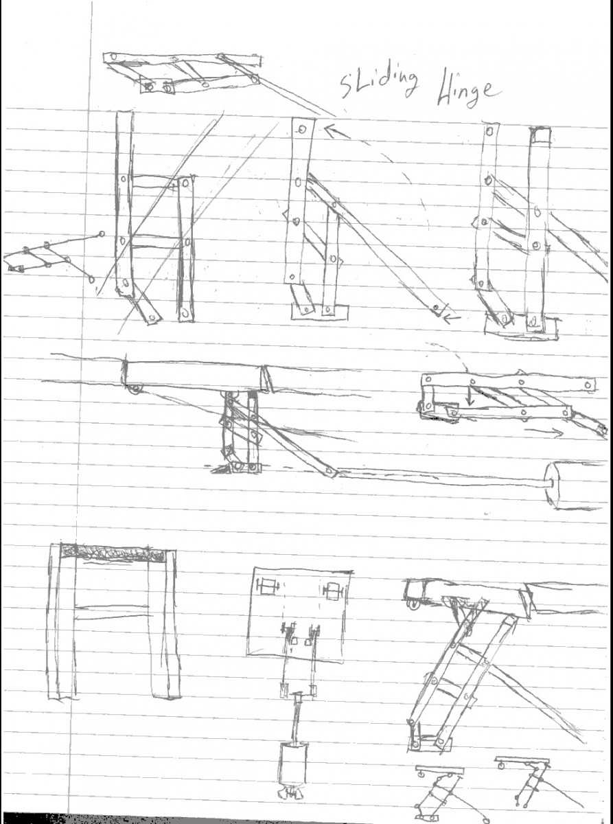
I finished a track and ramp for my model. The mock up the stud wall and triskets deck that simulates the parameters in the Voorhees theater floor. The ramp and track are fixed relative to the opening in the deck. The track has some rough corners that bind the platform but should be fixed with some smoothing.
I have moved the track wheels from the edges of the platform to the base of a center leg positioned in the middle, much like an R2D2 leg. This improved stability by supporting the center of gravity and use a ground level ramp instead of ones that would have to be suspended.
This design version does remove the redundant support from the track and wheels and rest the load solely on the legs of the platform.
Because of the sharp angle of the ramp, the track causes the platform to lift off of its front wheels before the legs begin to elevate the platform that could pose an issue binding with the deck.
I would want to see if a shallower ramp with a smaller angle or a smaller center leg could give me more room to clear thicker deck material for more structural integrity.
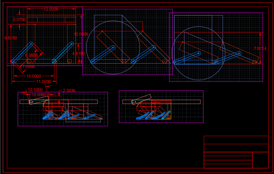
I continued to update my Auto CAD model and I started to document and capture the past versions of the model for my journal.
This is my first design, it utilizes the sunroof and cartage design. the piston that pushed the carnage forward, up a ramp would also compress a set of arms that would lift the back of the platform to be flush with the deck. The issue with this design is that it would rely solely on the strength and integrity of the piston for structural support, meaning a single point of failure could compromise the stage.
This is the dissection of the 4 steel bar window hinge that I found in a catalog. The arms of the hinge are each have 3 points of constraint to create 1 compound axis of movement.
I wanted to extend an bar to be perpendicular and flush to the bottom of my platform. A leg extending from the foundation to the hatch would provide significant support vertical compression and not rely on the piston for structural support when in position.
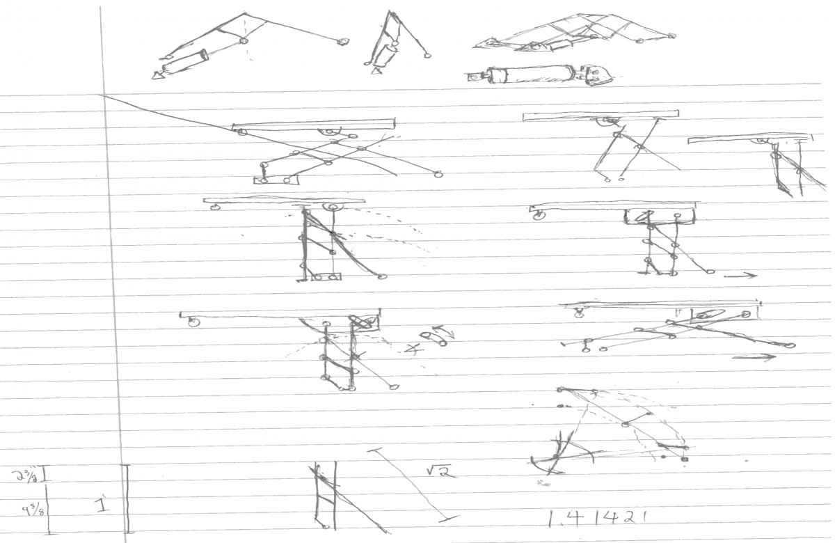
The next draft used the scissor lift idea but got rid of the ramp because it would not work with a single point hinge and kept inverting the platform. This design has four legs and would use cross bars to move the legs simultaneously.
This was reformed into the current design that uses a 2 part ramp to lift the stage to a preset level and then a vertical lift that moves the platform level with the deck as the legs are set into a vertical position.
Fighting with open lab to publish scans is challenging.
PDF’s do not show up as images so I need to save them as images, reformat them to 16bit color, then convert them into jpeg files because bitmap and XPS are insecure formats.
Automated trapdoor: Avoiding Pitfalls
Introduction
I am Andrew Ng, I am an entertainment technology student specializing in technical directions and lighting design. I have created and Automated trapdoor that can operated in a shallow deck and be safe resilient enough for the theater.
Materials and Methods
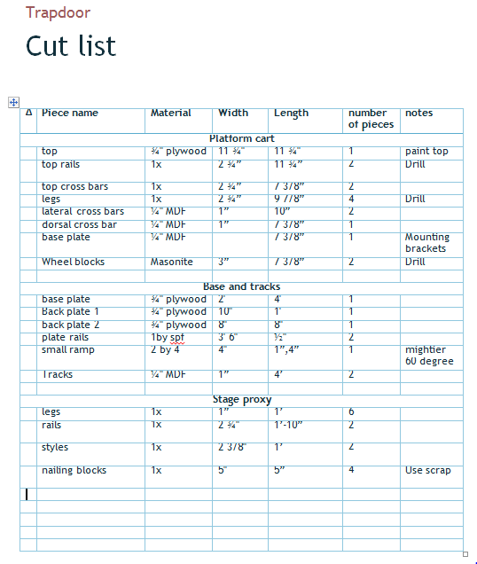
The trapdoor will be designed for a stress skin trisket and stud-wall deck. I will have a autoCAD model, a one to one proof of concept and several prototypes.
A four step design approach is used to test a hypothesis or design to progress the project to new milestones. It cycles begins with researching, then incubating and developing the approach or hypothesis, executing or building a model to test the hypothesis, they reflecting on the results and returning back to the research step to start the process over again with a new idea.
Results
The project gradually evolved from a theoretical sketches and a brainstorm of unrefined ideas into a computer drafted assembly and physical model that incorporates several existing ideas and patents to solve an novel problem with spacial constraints.
Conclusions
The trapdoor project taught me how to adapt, modify, and revise both my own designs and designs of other people. I learned how to reverse engineer structures into elements the I can use in future projects with drafting and modeling tools.
Literature Cited
US Patent Office R736001R
McMaster Catalog 4 bar steel hinge
Stud wall and Trisket platforms Yale theater PDF
Acknowledgements
John McCullough, Rudy, Remmy, Cortly Dennis, and Angelo
For Further Information
Contact Andrew Ng at Andrewj.ng@outlook.com
Leave a message at # (518)-712-9466
Visit the project website at https://openlab.citytech.cuny.edu/andrewng-eportfolio/
PDF available here:
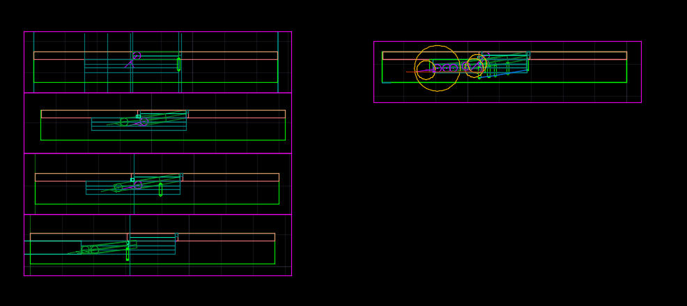
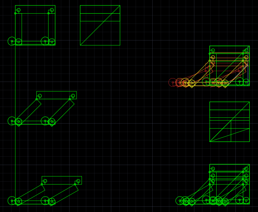
I worked in autoCAD to revise and model a new arm for the platform. I ran into autoCAD’s limitation in making moving model and had to map out the positions of the arms for each frame of movement. I used 3 frames and mapped an arc to determine the path of the trapdoor through the deck to estimate how much clearance each design would need.
Since the travel of the platform is a swinging arc, I would need a need to have a mitered edge or a method to swivel the deck out of the way so the trapdoor can shift into place without compromising the strength of the deck.
The OpenLab is an open-source, digital platform designed to support teaching and learning at City Tech (New York City College of Technology), and to promote student and faculty engagement in the intellectual and social life of the college community.