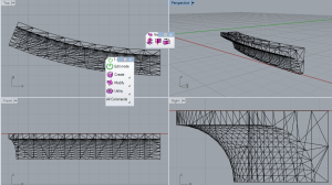
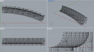
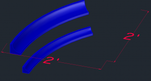
I have modeled and extruded samples of curved cove molding.
I limited the size to 2 square feet to fit on the working CNC machine.
To make a 3d curved extruded object, draw the object you want as a closed poly-line. Then draw the path you want it to follow as a line or poly-line. Enter the (Sw)eep command, select your object(s) , enter ‘B’ and select a (B)ase point, and finally pick the path you want it to follow.
Orientating which side of the path the base point is drawn against took some trial and error.
CAD and STL files Files linked below:
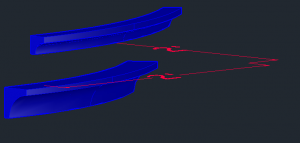
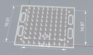
The size limitations for architecture’s working CNC machine are actually 14.8 to 15 inches square with the current bed configuration. The test sample needed be scaled accordingly and exported to Rhino.
Objects must be saved in their own cad file (without references to title-blocks) to open smoothly in Rhinoceros 5.0. Then the selected object can be exported as an SLT file.
Then they can be imported to architecture’s template.
Link to Architecture’s page: http://www.nycctfab.com/#!equipmentcncmachining/c7s5
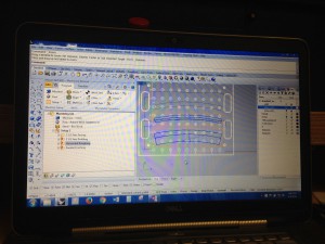
At the bottom of the page there is a folder, “NYCCTfab Template Files,” where you can get the “NYCCTfab_Roland_Standard_3Axis_pallet.3dm file to set up the CNC tray.” Import your STL file into the template and contact architecture to set up an appointment.
Appointments can be found in http://www.nycctfab.com/#!cnc-monitor-schedule/c1sh6
Update
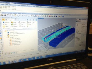
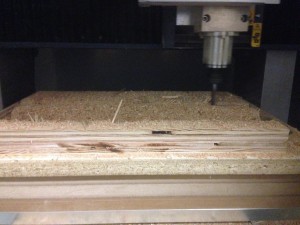
Since the CNC lab only has 1.5 inch wood bits until they can buy replacements, the 2.5 inch curved cove had to be cut in half and laminated later.
The CNC Roland machine is capable of routing a 16″ by 16″ sheet or block of plywood.
Tool paths can be adjusted to have more steps for more pierces definition to your virtual model, but this comes at the expense of more time for more passes and wear to the bit.
Software crashes hardware errors are inevitable but can be planned around.
Sample video:
The final piece came out a little rough but satisfactory the project.

