Subsea Actuators
The uniqueness of the underwater environment creates quite a few challenges and also dictates that well functioning devices have certain features in common. After all, these things are not meant to roll down the street! ROVs must be able to function at a considerable range of depth (i.e. any pressure) in case of unforeseen circumstances and those same circumstances also make it prudent to ensure that they have an extended operational life. This means streamlining actuator efficiency. In addition the design must include ease of access for repairs, adjustments and part replacement – otherwise you risk losing valuable time in the field. They need failsafe solutions for malfunctions so that devices aren’t lost and lastly (and one of the most obvious) is the choice of materials. Exposed parts must be seawater resistant.
Different types of actuators utilized in the design and construction of underwater ROVs.
Including:
Propeller Actuators
Thruster Actuators
Valve Actuators
Because the underwater environment is similar to space there are very specificrequirements. Control comes from the proper management of forward and backward thrust, roll, pitch, and yaw in relationship too buoyancy which is determined by depth. What are the actuator dynamics? That depends on the size and density of the ROV as well as its maneuverability requirements.
Below is a link to video of a company Videoray testing one of the thrusters they have available to the general public. Two Videoray GTO thrusters are used to drive the vehicle in the surge and yaw degrees of freedom. The thrusters are mounted directly to the rear endcap. Their optimal operating voltage is 24V, and they receive a max theoretical voltage of 22.2 V (V-batt).
https://www.youtube.com/watch?v=wxW-bDgxPAk
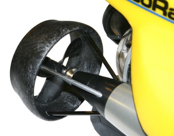
Here is a close up of the actual thruster-
It is highly rated and this view of the rugged molded thruster guard also shows the 100 mm propeller, and proprietary shaft cartridge seal which will they claim will last 100 hours plus depending on how the sub is driven before needing to be swapped out.
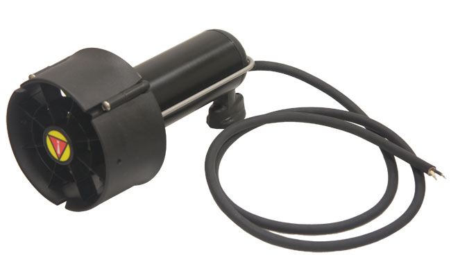
This is a Seabotix BTD150 thrusters:
These thrusters are often used as vertical thrusters to control pitch and heave, and as strafing thrusters to control sway. The vertical thrusters are mounted to cross beams below the fore and aft vertical members. The fore strafing thruster is mounted in front of the fore vertical thruster, and the aft strafing thruster is mounted below the rear endcap. The optimal operating voltage is 19.1 V, and they receive a max voltage of 22.2 V.
Valve actuators first became common in the 1970’s to control the ballast on large ships and are often used in more advanced ROV control systems. They are also a key component in underwater hydraulic systems and come in impressive array of sized and capacity.
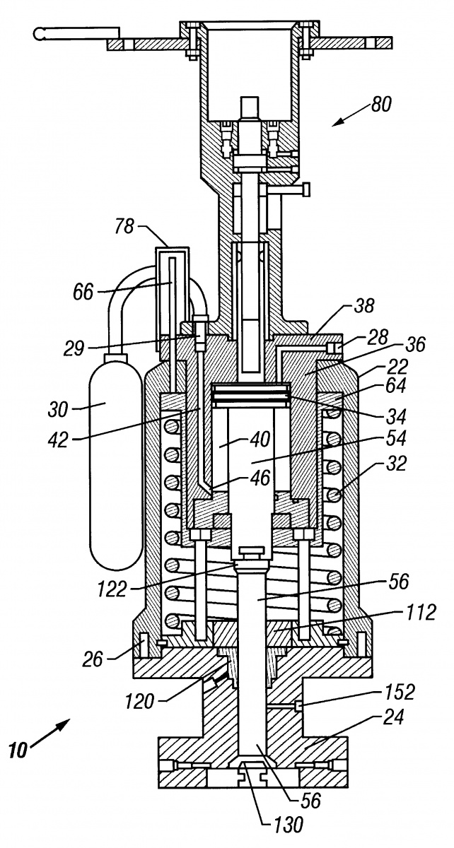
Below is a diagram of one and the abstract about it taken from the following site:
http://www.freepatentsonline.com/6609533.html
(please note – not in my words)
A subsea actuator and method is disclosed that includes all moving components mounted in a compact, concentric configuration. T. A preferably cup-shaped spring pusher is provided in telescoping relationship to the hydraulic chamber. A piston position indicator is provided which is connected externally to the hydraulic piston cylinder to avoid the possibility of hydraulic leaks due to the piston indicator. A manual override may be provided with a manual override indicator. The manual override indicator has a shorter travel length than the manual override operating stem to thereby reduce the overall length of the manual override assembly. The driving stem provides a removable connection to the hydraulic piston from the top of the actuator housing and a quick disconnect permits disconnection of the driving stem from the valve stem. In a preferred embodiment, upper and lower t-slot connections are utilized in the driving stem assembly. In a preferred embodiment, two back seat valves are removably secured to the driving stem to engage respective seats and provide additional sealing around the driving stem so as to prevent leakage between the valve chamber and actuator housing chamber. The high tension spring does not need to be removed to perform maintenance, and all wear items and seals are readily accessible. Change or replacement of the stem packing is made from the top of the bonnet to avoid dissasembling the bonnet to valve body connection. Pre-load bolts are used to adjustably preload the tension in the return spring. The height/weight of the actuator is significantly reduced as compared to prior art subsea valve actuators.
Sources
dspace.mit.edu/handle/1721.1/68953?show=full
http://seaperch.mit.edu/build.php
http://www.seabotix.com


