Objective- To take apart an FM transmitter, analyze it, figure out the chips used, and putting it back together with the goal of the device working.
Materials:
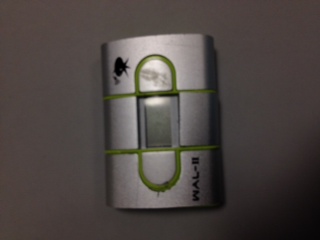
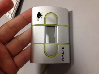
1. FM Transmitter
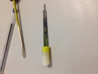
2. Phillips head screwdriver
3. Flat head
4. Mysterious flathead
Procedure:
1. We removed the green battery cap.
2. With a flathead screwdriver, we removed the top piece of the transmitter
3. We analyze the transmitter thinking that we were in a dead end, but then we noticed that the housing in the middle could be removed with some force involved.
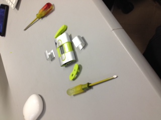
4. We asked the professor a question involving the device about breaking the plastic, but we got the okay, but not to do it on purpose.
5. We got the bottom piece of the device off, it was a little challenging because there was a tab in the middle to keep it from coming off, but we were successful. The little green tab was nowhere to be found.
6. Thinking we had to take the top piece off, we were actually able to slide the top out with a flathead.
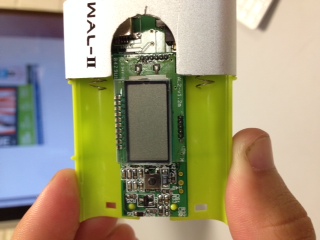
7. We analyzed the chip, noticing that it is not screwed into the transmitter, but it sits on top of the bottom.
8. Our classmates found the tab that flew towards him.
9. We finally took the top piece off with the help of a mysterious screwdriver, but we cannot take the chip out because it is soldered on to the battery coils.
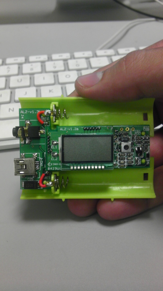
10. While noticing the chip, we saw that they used a BH1417F type chip.
11. After analyzing the transmitter, we will try to put it back together.
Results- We were given a FM transmitter, took it a part, experienced some challenges along the way, analyzed the chip, and put it back together successfully.