Sharon Miller Machine Research Paper


For my “Machine Research Project” I decided to discuss the homemade wooden rolling ball clock. In my research I found a few that interested me, however, the Turnvater Janosch pendulum version intrigued me the most, because of its design and accuracy. I will be discussing the Janosch version specifically within this assignment.

The wooden rolling ball clock is completely mechanical and requires no software, or electronics. The idea is to be able to tell time via a strategic chain reaction of events, similar to a Rube Goldberg machine, involving wood, plastic gears, small steel balls and a pendulum. The body of the clock is made of wood, with pathways for the marble balls to travel on built out of steel wire. The clock runs for 12 hours and is only off by 1 second within that entire time. The clock has 3 levels of wooden traps, which denote time and hold the steel balls. The clock is set to work in 1 minute, 5 minute and 1 hour increments. Each minute that passes, a steel ball is lifted up from the base of the clock and sent down one of the steel wire pathways to its corresponding time trap. When specific time increments are reached, such as 3:00 or 8:45 for instance, the steel balls are released from the traps and sent back to the base, where the process repeats all over again. The clock is weighted by a 5 lb flat iron and driven by a pendulum, which swings in 1 second intervals.

I thought this machine was really cool because of how accurate it was in telling time and how much thought and logic had to be involved to create it. I liked the design aesthetics of this machine and could easily display this machine in my home. I am also wondering how I could possibly one day build one myself. Below is a link to the wooden rolling ball clock discussed in my assignment: https://www.youtube.com/watch?v=UHBHCsrqYMw Below is a link to a similar clock: http://www.lisaboyer.com/Claytonsite/celebrationpage1.htm

Sharon Miller Machine Research Paper

Posted in Uncategorized | Leave a comment

Sharon Miller Prototype Report

My prototype design test is the moving picture. The requirement is to create a painting on a wall that can be easily changed out to another painting in between scenes. My instant thought was a moving scroll that could be manually rotated to reveal a new picture In the frame visible to the audience. This idea came from a childhood experience when I owned a toy television, which had a rotating image to create the illusion of a television show actually playing.

For this prototype, I drew various sketches and researched information online. I looked for information on scrolls and gears, as well as how the toy TV I used as my inspiration was made. I built a wood box Open frame, which I attached to The back of a scaled down model stage flat. I then inserted two 1 1/2″ wooden dowels on both ends of the frame. The dowels act as the mechanisms to rotate the attached picture. I used a strip of brown paper to act as the temporary canvas picture to see how the prototype would work. The ends of the paper were attached to both ends of the dowells with gaffers tape for now. My original plan was to have the picture canvas wrapped continuously around the dowels, but when I tried rotating the scroll I ran into the problem of the picture not being able to rotate smoothly and the picture getting caught between the gears. Therefore I halved the picture so it could rotate from left to right or vice versa with two pictures side by side on the paper instead of front and back.

I feel my research was thorough enough for me to understand my direction and how to build my first prototype. I am not sure if I would make any major changes to my prototype as when it was tested it did exactly what it was supposed to do. I may add handles to the dowels for ease of use. I also plan to replace the brown paper with actual canvas. Some cosmetic adjustments are also in order. I really like this project because even though a scroll seems easy to create on first glance, it actually isn’t and required me to do a lot of critical thinking, which I appreciated.


sharon Miller Prototype Paper

Posted in Uncategorized | Leave a comment

Prototype Reflection

My prototype were the elevator doors. I used google pictures and YouTube to see pictures of simple lift door operation, and consumer grade elevator doors. I chose to use the lightest materials because I have created a scale version of Hollywood-style platform. I used 1x pine as well as 1/8″ Lauan for the lid. Most of the planning went into the mechanism and how it will operate. There were also a few things that needed to be factored in when the scale model was completely built. The idea of my V-groove wheels that will allow the doors to slide freely on a track worked. However, the alignment of the track itself was giving the most trouble. In a real life situation, choice of material for the build would be metal. I have learned that the alignment of the top and bottom tracks are very tedious and must be precise to some degree. I learned that proper planning and further research will help me much more in future projects.

Posted in Uncategorized | Leave a comment

Charles Bowden Prototype Reflection

Description

  • I was testing to see if I could move marbles
  • Google search engine
  • I used foam board because I just wanted to see how everything would be placed and blocks would move
  • stressed, tying to figure out what would work and I just dove in to better get an understanding

Analysis

  • the framing , at the time I had not reached the actual mechanism
  • I had to alter the from the research to make it work for me
  • no/yes. needed to research more once i found a basis of what I wanted
  • no physically, theory yes
  • something to hold marbles in place and a hole to fill

Application

  • The compartments that I would need to create
  • devote more time in every step, not panic as much, play with the ideas in real life and its ok to go so far in the process and repeat to fix or extend


Posted in Uncategorized | Leave a comment

Prototype Reflections

Description:

My prototype was to see if the elevator doors could slide. To see how they worked I searched various sites such as How It Works, Wikipedia, and few documents. I also watched YouTube videos to see how the machine worked behind the panels. Since this isn’t a real elevator door but a stage set I made the flat and doors for this prototype half 1×3. I would normally use 1×3 wood but I was making a smaller scale to make up for materials. The prototype didn’t have plywood face because I wanted to just see if the skeleton would work. I had the the concept and afterwards I made a cut list of what I needed to build and used string to test the doors.

Analysis:

The doors did slide but not with best efficiency. They were clunky and to make them smooth I would need a track. I’m glad I tested because it’s obvious I need a short platform with tracks on the door, now I will have to just to make it actor proof. I would only consider putting the face of the flat to see if that would not be too tick. The model also was short with framing that was weaker than the 1×3 that will be actually on the finished project which will make it sturdier.

Application:

The track has to be applied and a better path for the doors on the top, maybe another track. I’m also planning to put a motor or pneumatic device to make the doors open without stagehand help. I definitely should’ve listed out all the specific materials and hardware needed with my concept and will need that for each project in the future.

Posted in Uncategorized | Leave a comment

HH Prototype

Problem: How is the roach going to move from one hole to another while looking organic?

Observation: I noticed during the presentations that several of the roaches with the wires in them didn’t move with the magnets. This shows that using magnets in this way wouldn’t be fully effective for this project. We would then have to figure out an idea that would make the roaches move while making it look natural.

Concept Sketch:
image

(The photo is slightly blurry, and I just realized that
I forgot to add the other holes in the front view. )

The motor would operate the whole assembly. As the motor moves, it causes the roach to move as well. Thus, making it go in and out of the holes within the lauan.

Posted in Uncategorized | Leave a comment

Cabinet Prototype Reflection

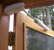
For my prototype, I constructed a cabinet that opens and closes ‘magically.’ I chose this project because I wanted to build a small machine/mechanism that used the pneumatic air cylinder as its actuator. The hinged door seemed to lend itself well to using an extendable cylinder. It reminded me of screen doors that use a compressed vaccum air cylinder as its mechanism to close automatically. Here is a picture of such a screen door:

hinge

To start, I measured my home kitchen cabinets to determine the general size of my cabinet. After I cut all my pieces and assembled the side, door, and base, I attached one end of the double action air cynlinder to the base, and the other end to the door. The main challenge I had was understanding how to secure the two ends of the cylinder. At first I thought I might have to build at least one track for one end of the cylinder to slide as it pulls or pushes the door, but then John showed me this was unnecessary. It turned out that both ends of the cylinder simply need to pivot to achieve the necessary pushing and pulling of the door. The next challenge was choosing a cylinder of the proper length to successfully open and close the door completely. Luckily the first cylinder I tried ended up being best suited for the task. I aligned the cylinder along the receding edge of the base so that it was as hidden as possible. Then, I attached the air hoses and tested the mechanism. As expected, the door movement was too abrupt, and I had to adjust the valves of the cylinder to limit the speed of the air flow. However, even with the proper air flow, I noticed the door of my cabinet never fully closes. This is the primary issue that I will try to fix for the final version of this project.

Working on this project made me realize that had I observed similar hinge mechanism around me more closely, I would have realized that I didn’t have to build a sliding track, and instead focused on creating pivot. Although I had a general sense of what needed to be done and I knew it was possible based on my cursory observations, I didn’t do my research as thoroughly as I should have and almost wasted time building a sliding track.

My main challenge for the final project is to experiment with the placement of the cylinder so that the door closes fully. I expect that this might have to come at the cost of the door opening fully the way it does already, or at the cost of the cylinder being more visible, since the cylinder size is fixed. But this is only a conjecture.  I hope I can find an arragement that satisfies both the requirement that the door opens and closes fully and that the actuator is hidden. I will also experiment with attaching a shelf that hides the cylinder.

Posted in Uncategorized | Leave a comment

Matthew Durnin “Picture Change”


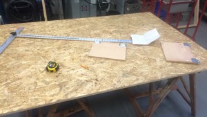
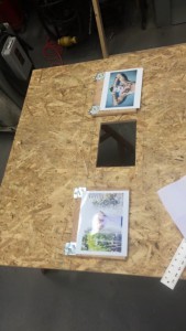
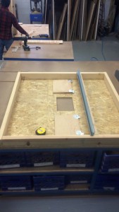
IMG_5918 IMG_5919 IMG_5920 IMG_5921 IMG_5922

I designed my prototype to change pictures with out the frame ever having to be removed form the wall. I did most my research inside the store “lowes” seeing what looks best and getting to see how the tracks work. I used wood ply and studs cause it would me it strong and sturdy. And using a metal track. My process was research then design them gather materials then build. The track worked and the picture sliders worked great along with the stoppers. Testing this all out was adequate. My prototype is not exactly how my final version will look. Its too big of a piece for me. What be different in the end is the height of the project. I learned having everything planed out while making your sketches of your project and foreseeing problems on paper, will help you out a lot.

Posted in Uncategorized | Leave a comment

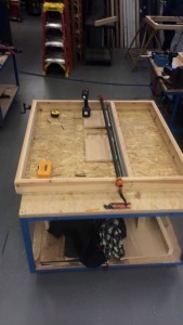
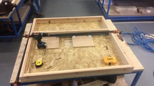
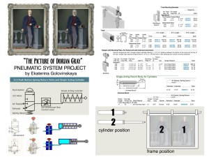
Picture Prototype

frame project

I’ve decided to make a prototype of a moving picture on a wall.
While I was drawing the idea on paper, I was trying to decide how I’m going to build this project. When I had an answer in my head, I started looking for sources in Internet that could match my idea. My thought was to build a “sliding door” with two pic­tures on it using pneumatic. So, I started looking online how people build sliding door, and found a blog that helped me to build my prototype.

http://​www.​ins​truc​tabl​es.​com/​id/​Air-​Powered-​Star-​Trek-​Style-​Door/

I chose pneu­mat­ics to move my pic­ture, I think this is more of­fi­ciant way to build the­atre re­lated prod­ucts and also I wanted to test my­self. Work­ing on pneu­mat­ics on paper (and not only pneu­mat­ics, al­most every­thing) doesn’t give you enough un­der­stand­ing. TEST­ING is a main key!

When I had an an­swer how to build mov­ing pic­ture I started look­ing for ac­ces­si­ble ma­te­ri­als: mount­ing brack­ets, tracks, cylin­ders, etc. Most of the ma­te­ri­als I found at McMAster.​com.

I started a process from build­ing the mov­ing part in my pro­ject, test­ing it (had some mis­un­der­stand­ing which way cylin­der goes, while it’s ac­ti­vated ), and then cre­at­ing a frame for it.

12243601 10207995143186544 273504399 n

I think my over­all process went smooth, I had good sources at the be­gin­ning. For my first pneu­matic ex­pe­ri­ence I’m happy with the re­sult, my model is ac­cu­rate enough – it works!

In real life things depended on a completion of overall production with tones of projects like this one, and things can change by a specific task, like weight, position, noise, speed, size, etc. And I’m sure my project will be different in a way in a real production.

Posted in Uncategorized | Leave a comment

Prototype Reflections – Painting Swap

Description

My prototype was designed to swap a painting/portrait from one to another. For this project I researched how counterweight systems worked, which I found over the web. The materials I used was 1×6 pine, 1/4″ MDF, 1/4″ lauan, and tie-line. The hardware consisted of two pulleys, one screw eye, and one screw hook. The beginning of the process started with me figuring out the dimensions of the flat itself, and creating the draft for it. Once that was done, I started building the prototype. After the first test, I realized that there was a lot of needed alterations.

Analysis

The prototype itself worked. I had a piece of lauan at 2′-1 1/2″ x 10 1/2″ with both paintings on it that would move up and down. I was able to change it from one portrait to the other, however I realized that there was nothing preventing the piece of lauan to stop moving. So I had to add a stop block on the top and bottom of the lauan at equal distance of the size of the portraits. Then I added a piece of plywood to the sides and behind of the lauan to prevent it from moving side by side and backwards. When I initially did my research and planning, I didn’t account for that problem until it actually occurred. I personally feel that I made an accurate model because it did what it had to do, but there are always room for improvements.

Application

While working on this prototype I’ve learned that nothing will be one hundred percent perfect. I spent a lot of time on trying to get it as perfectly and accurately to the drawing as possible. Instead of answering the question itself, of how the portraits will change. Now that I’ve answered everything, for the next version all I have to do is add in all the corrections. This project taught me that sometimes you just have to start building in order to know what needs to be fixed. Though it’s great to do a lot of research, I spent a lot of time over thinking my design rather than actually trying it out. Once I started building it, the process started to flow more easily.

Posted in Uncategorized | Leave a comment