

Scale Problem
Hey Prof.king its Rangel Ulerio from building tech I just had a question about scale, How do I emphasize on the section without having different scales? If I change the scale then the section would look to small. I attached a file.
Due for next class
- Complete the structural portions of your building
- Concrete
- Foundation Wall and Footing (basement to level 1)
- Isolated concrete footings and column (below slab to slab)
- Foundation Slab
- Steel
- Interior Columns – Basement to roof (have a joint 3 feet above level 2)
- Perimeter Columns – Start at Level 1 to roof
- Steel Columns (level 1 to roof) Remember to set -5″ Z height
- Show column tags
- Floors
- 3″ LW concrete on 2″ metal deck (level 1 to roof)
- Exterior Wall
- Add a placeholder wall – Level 1 to Parapet
- Plan development – study your entry level plan. Work out the dimensions of the different walls and be prepared to draw in class.
- Concrete
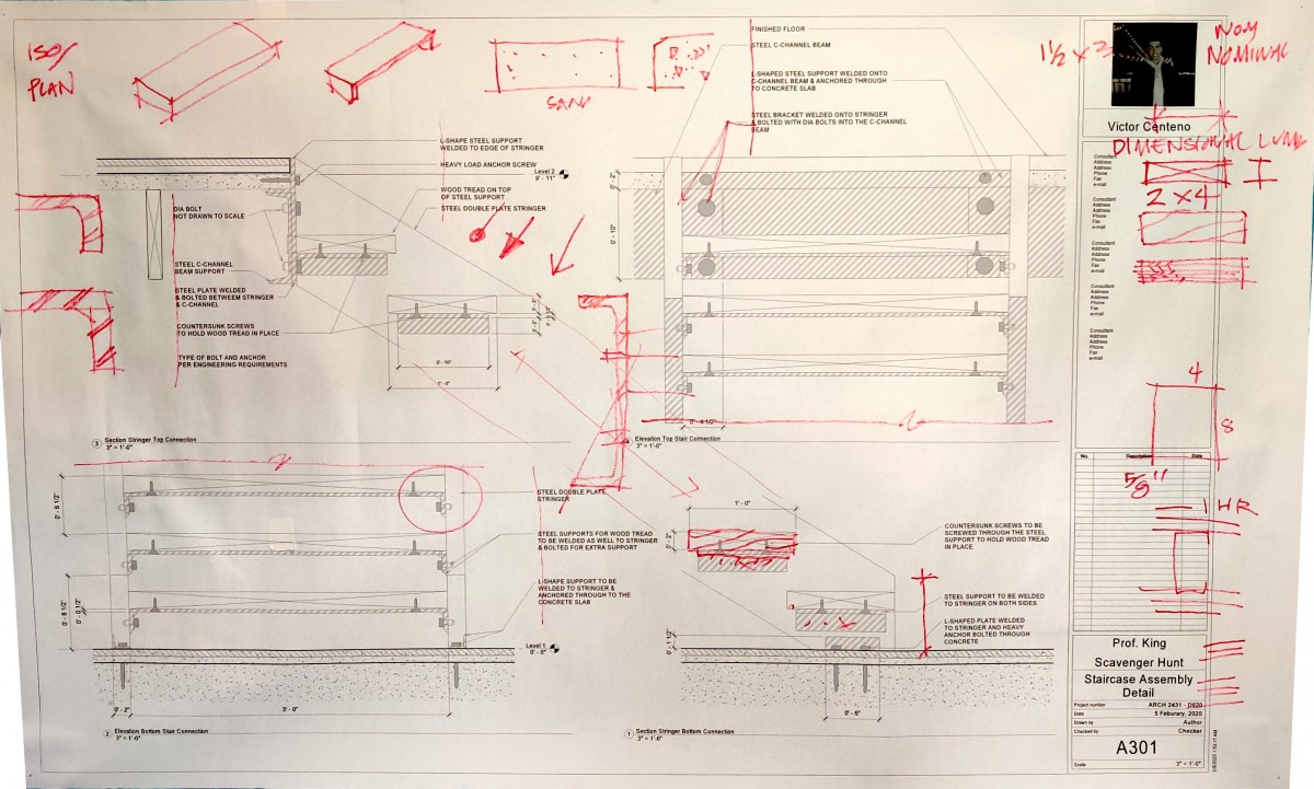
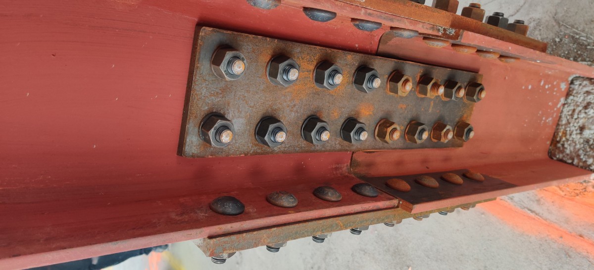
Victors Scavenger Hunt Detail Sheets & Steel Photo

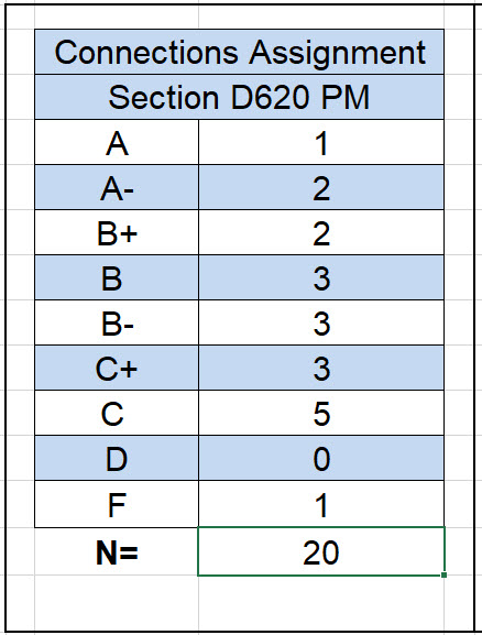
Grading Statistics for Connections Assignment
All the grades are posted. I am awaiting the posting from 1 student.
In addition to the class pinup grading included a review of your Revit files and families. In this review I looked for proper naming of families, correct use of reference planes and parameters that controlled the model. I also looked for sheet layout and development of details including the views shown and the inclusion of notes, hatch, dimensions etc.
Case Study Team Presentations
Case Study grades – first column is by team and then by individual. For example 1 team got B+ x 2 team members = 2 individuals.

Current Assignment – Case Study Building – Posting for Monday by Midnight
Complete the following for Monday evening
- Create a new project file – give it a good name
- Should include your name, the semester & course, your building, your professor
- Create all necessary Levels – and set their heights –
- If your building does not have a basement level please add one
- Add your grids
- You should have a minimum of two intersecting grids (1,2,3 & A,B,C)
- If your building has the same layout of grids on every floor make certain your grids show on every level
- If your grids are complex and change on different levels complete at least the first level (entry level)
- Add dimensions for all your grid lines – do this only on Level 1
- Sheet and Scale
- Set the scale of your plans to 1/8″=1′-0″
- Using 1/8″ scale attempt to format the grids on a 22 x 34 scale. If it does not fit then try larger sheets (30×24, 24×44) but do not adjust the scale.
- Do not delete any attempts to layout the sheet from your file.
- If it still does not fit just let it run off and bring it to class.
- Modify the titleblock to include your photo and name, list your team mates for the project, name of the project, course, semester, professor
- Post on Blackboard (by end of day Monday)
- Revit file
- Plotted PDF – this would be for your sheets. If you lay out your project on different sheets then they would all be included in the PDF – a single PDF please.
First Progress Individual Submission – Building Case Study
Upload your Revit file and the latest PDF of your sheets to Blackboard.
For this submission you will need to complete the following:
- This is not a team submission – each student must complete this work
- Create a new project file (give it a proper name)
- Add Levels & Grids as necessary for your building
- You do not need to complete this for class but you must show that you have given it some effort.
Final Submission for Connections Assignment
This is your final submission. Be certain of the following:
- Upload both your Revit File and a Single PDF to Blackboard
- Your Revit file will contain all of your families – so you do not need to upload these separately
- Print the first sheet as 11 x 17 and the second detail sheet as 22 x 34 – full size.
The second sheet is more important than the first one. I expect most of you to have a very similar first sheet. This sheet will show your entire updated model – with keys for callouts showing details shown on the second page. A final submission that includes only the first sheet will not receive a grade better than a C – which is minimally passing.
The majority of your grade is based on the work you show on the second sheet as well as my review of the construction of your Revit file. For the second sheet you must include the following:
- Larger Scale callouts of specific connections (for example the footing to baseplate connection)
- This specific detail study would require matching and aligned plans and one section. In this specific case only 1 view other than the plan is needed as additional elevations or sections do not show any additional information. For this view the section should be cut through the center of the hold down bolts.
- Typically for other details you are showing you will need a plan view and two other (section or elevation views) plus an isometric.
- Always include an isometric for each study
- Images should not display shaded – but as hidden lines.
- Always include Annotation (Notes with Leaders and Dimensions)
- Where appropriate add “detail items” to show materials or add the “break line”
- In your families assign proper materials so they show properly in section
- Add a drawings list into your titleblock above the sheet number/name area. This “view” can be put on more than one sheet – so put it on both.
- It is OK to create more detail sheets if necessary.
Careful of over constraining a model
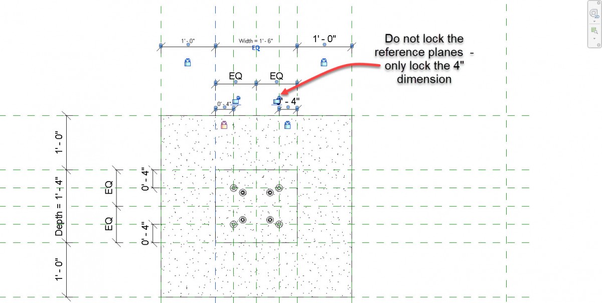 In the example above the student received a conflict message that the model was over-constrained when trying to adjust the parameters for depth or width. This was related to the second set of reference planes put in place to move the locations of the bolts when the parameters were adjusted.
In this instance the student has locked the the 4″ dimensions correctly but has also locked the second set of reference planes – which then cannot move. When the depth or width is modified the locked 4″ constraint attempts to move the reference planes – but as these are locked there is a conflict and the error results.
Be certain only to lock the 4″ dimension and
not the secondary reference planes.

