OBJECTIVE
For the purpose of this laboratory experiment, the given complex dc circuit should be constructed and analyzed by taking measurements as well as by doing calculations. The purposes of this laboratory experiment is to demonstrate ability to use Thevenin theorem to simplify a complex circuit as a Thevenin equivalent circuit and be able to find the maximum power delivered to the load resistance in the circuit. To analyze a Thevenin’s circuit and maximum power transfer of the given dc circuit using matlab. In this laboratory experiment, the results obtained from matlab will be compare with the experimental results.
INTRODUCTION
Thevenin Theorem allows to simplify a complex dc circuit with a load components into a simpler circuit. Thevenin theorem allows to reduce the numbers of components in a circuit into only two components; a voltage source (Thevenin equivalent voltage) and an equivalent Thevenin resistance, and the load component (Rload) For example:
Thevenins theorem allows to investigate the behavior of different load components in the same dc circuit without having to analyze the entire circuit every time the component is change.The maximum power delivered to the load components will occurs when the load resistance and the Thevenin resistance have the same resistance value. The Maximum power delivered to the load resistance can be find as follow:
Pmax=ETH^2/4RTH
EXPERIMENTAL
Procedure:
For the purpose of this laboratory, construct the following circuit.
Circuit A
Thevenins equivalent circuit & Calculations:
In the original Lab manual, the resistance value in circuit A should be 91 Ω but for the physical construction of circuit A, the resistance used for R1 was 100Ω. Make calculations to determine the Thevenin equivalent circuit.After constructing circuit A, use a potentiometer as R load to randomly select a value for R load. Then, measure the current through the load resistance, the thevenin equivalent resistance and the thevenin equivalent voltage.
Calculate the load resistance value using the measured values for the Thevenin equivalent circuit and Maximum power transfer- Matlab
MathLab Code
Yasin Khan
%lab 3 - Thevenin Theorem and Maximum Power transfer
clear
clc
% Ask the user to input information
R1 = input('Enter the value of R1 in Ohms ');
R2 = input('Enter the value of R2 in Ohms ');
R3 = input('Enter the value of R3 in Ohms ');
R4 = input('Enter the value of R4 in Ohms ');
E = input('Enter the value of the voltage source in Volts ');
% Calculation for RTH
RA = (R1*R3)/(R1+R3);
RB = (R2*R4)/(R2+R4);
RTH = RA + RB;
% calculation for VTH
VA = (R3/(R1+R3))*(E);
VB = (R4/(R2+R4))*(E);
VTH = abs(VA-VB);
% calculation for VLoad,Pload,Rload and Pmax
IT =(E)/(RTH);
RL = 10:1000;
VL = IT *(RL);
PL = VL.*VL./RL;
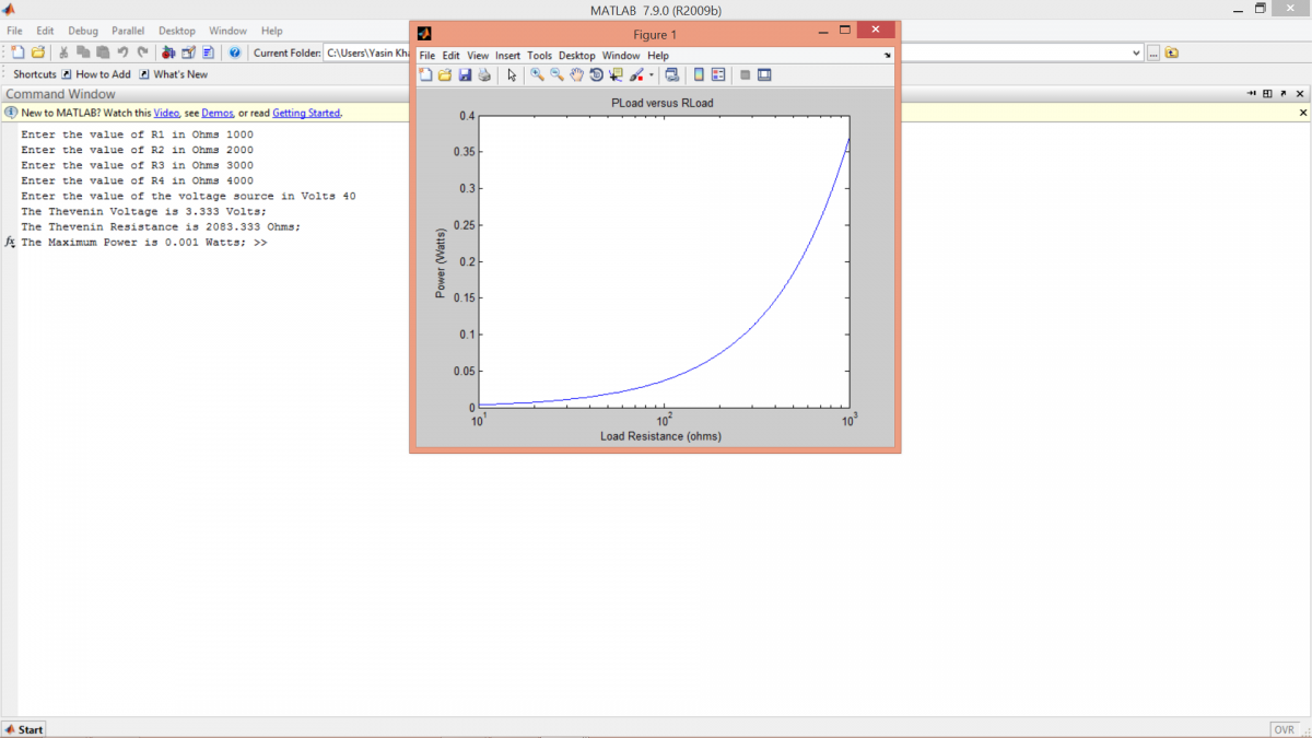
semilogx(RL,PL);
title('PLoad versus RLoad');
xlabel('Load Resistance (ohms) ');
ylabel('Power (Watts)');
PLmax = ((VTH^2)/(4*(RTH)));
%Display for VTH,RTH and PmaxLoad
fprintf('The Thevenin Voltage is %4.3f Volts; ',VTH);
fprintf('\nThe Thevenin Resistance is %4.3f Ohms; ',RTH);
fprintf('\nThe Maximum Power is %4.3f Watts; ',PLmax);
Results