D.T.S Designs- Laundry Basket

Abstract: The purpose of creating a multifunctional laundry basket is for people to adjust to something that is more convenient when it comes to doing laundry. My team and I have done our research and discovered that most people that do laundry, either at home or a Laundromat, normally use the single laundry basket or bag to place their dirty clothes in, and then clean clothes after they are finished. D.T.S designs have come up with a solution to fix most people’s problems, by creating a laundry basket that will be designed for an all-in-one purpose.

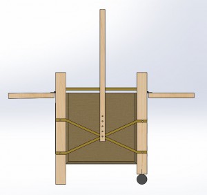
Introduction: Our objective plan is to create and design a multifunctional laundry basket to fit everyone’s daily needs; from having a simple laundry basket which is used to place unclean/clean clothes into it; compared to something that is an all in one purpose. D.T.S Designs has come up with a great idea that can be more convenient for you! We have transformed a simple laundry basket, to a multifunctional laundry basket, which includes: wheels – better movement, one large hamper separating into two- it can hold your white and color clothes, a kangaroo sized pouch – to hold your detergents, a foldable axis – to simply place into small places, adjustable rods – to hang clothes, and a flat table top – for you to fold your clothes. Our product will blow your mind to know that you have an all-in-one basket to make your weekly routine laundry day much easier. We want to make sure that the design is fully tested and it is ready to be published on the market without any mechanical failures that could cause injuries. We also designed the front and back layers of the laundry basket to be made out of maple wood, and the bags are made from cotton.

Project Boundaries: To make sure it’s fast and safe to use. And that it’s able to support a large amount of clothes. We also want to make sure that its environmental friendly by using 80% or recycled resources to have the designed mass produced.

Target Market: Anyone who does laundry in their- houses, apartments, laundromats, hospitals, dorms, hotels

Design: For our design, we want to primarily catch local Laundromats attentions because they would be the first set of companies to purchase and test the product out and ship them to the local laundromats. We figured it would be a great idea to let the local laundromats test them out first, therefore people in the neighborhoods could get a better hands on feel towards them.

Screen Shot 2015-04-10 at 3.32.08 PM

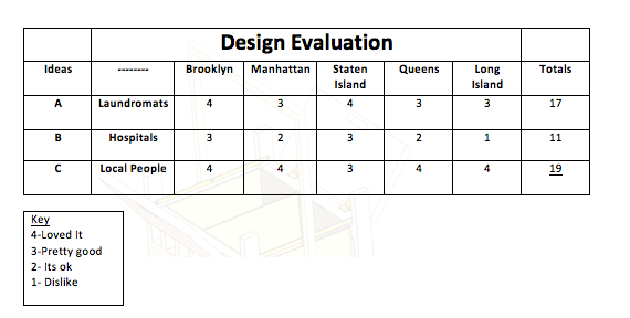
By understanding our Design Evaluation, our first idea we tried was to release our product in the 5 boroughs in New York. As you can see Laundromats have a scale number of 17 which is good level. But when we released to the hospital they were a scale number of 11, they were the lowest counted some hospitals requested a better material and all attachable wheels for better movement. The last scale rating was local people, we found surprising that it was the highest among the rest. We knew that people would love the design because we were the first to create it. The way we evaluated our numbers was once we released the product, we attached a survey for feedback for us to create to satisfy you.

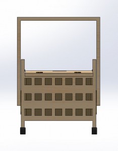
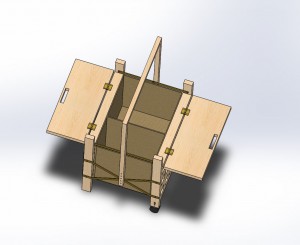
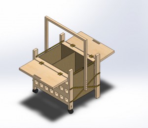
Final Assembly 

 

front view iso top isometric view side view

Continue reading

Reverse Engineering Project

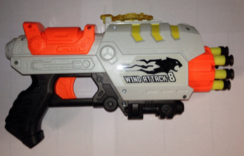
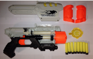
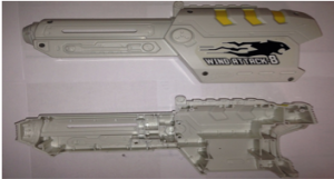
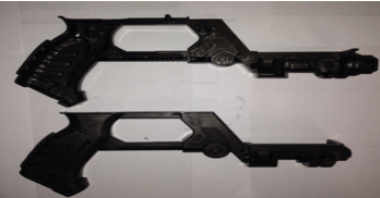
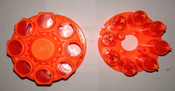
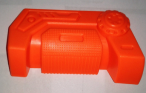
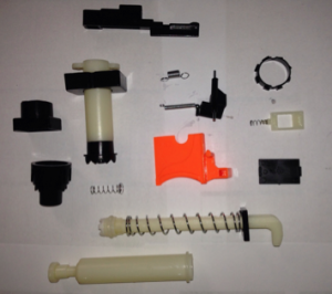
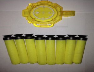
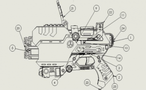
Overview: The object that I chose for this reverse engineering project is Nerf Gun. (Fig. 1) This object contains about 23 components and the material of this object is mostly made out of polyester resin. The company designed this twin-pack nerf gun package attached along with two scopes, 20 darts and 2 plastic cans. This nerf gun can hold up to 8 darts at once and it’s easy to pump. I began by taking apart and started to document all the components. (Fig. 2a-2g)

Screen Shot 2015-04-10 at 10.33.01 AM

                           Fig. 1

Screen Shot 2015-04-10 at 10.33.01 AM

                       Fig. 2a

Screen Shot 2015-04-10 at 10.33.13 AM

                        Fig. 2b

Screen Shot 2015-04-10 at 10.33.13 AM

                          Fig. 2c

Screen Shot 2015-04-10 at 10.33.23 AM

                         Fig. 2d

Screen Shot 2015-04-10 at 10.33.33 AM

                          Fig. 2e

Screen Shot 2015-04-10 at 10.33.39 AM

                           Fig. 2f

Screen Shot 2015-04-10 at 10.33.45 AM

                          Fig. 2g

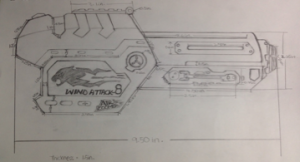
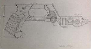
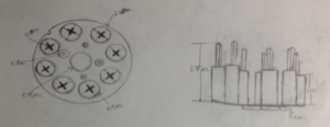
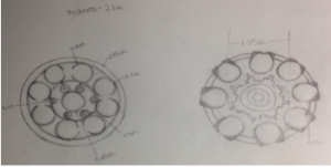
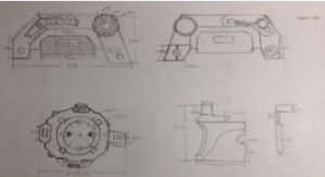
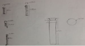
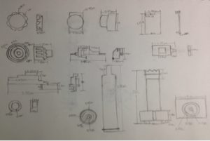
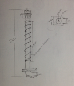
Procedure: I started up with sketching the components by using my hand. I drew the front view and side view of most the components so I can keep track of all the thickness. This object has a lot of minor details that couldn’t capture the dimensions by using ruler, therefore, I use caliper to measure and label the dimensions in inches on the sketches I did. But overall, I used ruler to measure all of the components. (Fig. 3a-3h) 

By sketching out the components, it helped me understand the geometric shape. It was helpful and able to understand more of which features to use and works for the best to which components. Cache, barrel tubes, handle and pulley were the main components that I focused on the most. In order to have an accurate reference point, I began all my drawings from the origin point.

Cache, handle, barrel tubes and pulley have a lot of details to work on. I used Extruded Boss feature to create the bodies on most of my parts. For the handle and pulley, it was done with Extruded Cut feature, Chamfer, and Fillet to create the angular shapes and details and I also used Hole Wizard to drill holes to insert the hardware.

Barrel tubes were created by Extruded Boss feature, Extruded Cut, Chamfer, Reference Geometry Plane and Circular Pattern tool. I used the Reference Geometry Plane to create the surfaces by offset to the height on part. In addition, I used Circular Pattern for the circles so I don’t have to sketch it one by one.

Cache was done it with Extruded Cut feature, Extruded Boss feature, Chamfer, Reference Geometry, and Shell. I used Shell feature after I done created the whole details of part and shell it inside of the part.

To create the dart, I used the Right Plane to sketch on and used Revolved Boss/ Base the solid part then Extruded Cut the inside to create a hole. However, most of the components, such as: Barrel, Base, Rect_Ring, Circles_Ring, Trigger_Support, Rect_Support, Valve Plug, Cap, Cylinder_Tube, Trigger, Scope, Ring and Air Restrictor were created by using the Extruded Boss feature, Extruded Cut feature, and Reference Geometry Plane. The springs were created by Helix/ Spiral and Sweep feature. The Helix/ Spiral can create the circle into spring and sweep to add or remove the thickness.

Screen Shot 2015-04-10 at 10.50.01 AM

                     Fig. 3a

Screen Shot 2015-04-10 at 10.50.09 AM

                    Fig. 3b

Screen Shot 2015-04-10 at 10.50.16 AM

                     Fig. 3c

Screen Shot 2015-04-10 at 10.50.21 AM

                     Fig. 3d

Screen Shot 2015-04-10 at 10.50.26 AM

                      Fig. 3e

Screen Shot 2015-04-10 at 10.50.30 AM

                      Fig. 3f

Screen Shot 2015-04-10 at 10.50.35 AM

                      Fig. 3g

Screen Shot 2015-04-10 at 10.50.40 AM

                   Fig. 3h

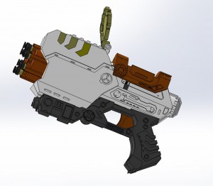
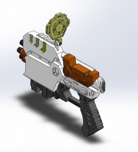
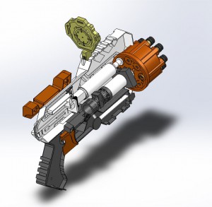
Results: Final Assembly- 23 components

iso side

                Isometric View

sectional left

                 Side View

sectional side

               Sectional View

Screen Shot 2015-04-10 at 11.04.58 AM

                Detail View

Discussion: The final assembly of nerf gun was necessary fully defined but it didn’t combine well. I tried to make it as realistic as possible. I learned that every component must create in order to achieve the assembly results. What makes me struggle the most is mating every components together; it has to match every angle limitations to work for a motion analysis. In fact, the process of creating the components was much easier than doing the assembly. I also learned the difficulty of reversing an existing object to a drafting design and perhaps into a new motion designs.

Continue reading