
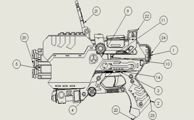
Overview: The object that I chose for this reverse engineering project is Nerf Gun. (Fig. 1) This object contains about 23 components and the material of this object is mostly made out of polyester resin. The company designed this twin-pack nerf gun package attached along with two scopes, 20 darts and 2 plastic cans. This nerf gun can hold up to 8 darts at once and it’s easy to pump. I began by taking apart and started to document all the components. (Fig. 2a-2g)
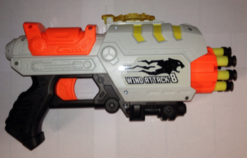
Fig. 1
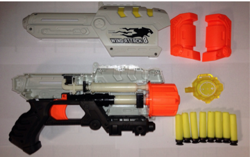
Fig. 2a
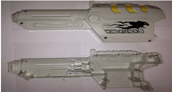
Fig. 2b
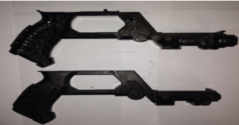
Fig. 2c
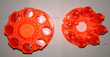
Fig. 2d
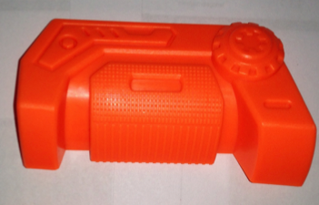
Fig. 2e
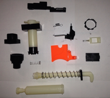
Fig. 2f
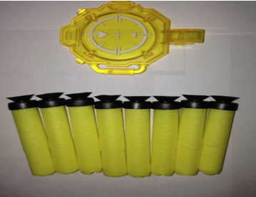
Fig. 2g
Procedure: I started up with sketching the components by using my hand. I drew the front view and side view of most the components so I can keep track of all the thickness. This object has a lot of minor details that couldn’t capture the dimensions by using ruler, therefore, I use caliper to measure and label the dimensions in inches on the sketches I did. But overall, I used ruler to measure all of the components. (Fig. 3a-3h)
By sketching out the components, it helped me understand the geometric shape. It was helpful and able to understand more of which features to use and works for the best to which components. Cache, barrel tubes, handle and pulley were the main components that I focused on the most. In order to have an accurate reference point, I began all my drawings from the origin point.
Cache, handle, barrel tubes and pulley have a lot of details to work on. I used Extruded Boss feature to create the bodies on most of my parts. For the handle and pulley, it was done with Extruded Cut feature, Chamfer, and Fillet to create the angular shapes and details and I also used Hole Wizard to drill holes to insert the hardware.
Barrel tubes were created by Extruded Boss feature, Extruded Cut, Chamfer, Reference Geometry Plane and Circular Pattern tool. I used the Reference Geometry Plane to create the surfaces by offset to the height on part. In addition, I used Circular Pattern for the circles so I don’t have to sketch it one by one.
Cache was done it with Extruded Cut feature, Extruded Boss feature, Chamfer, Reference Geometry, and Shell. I used Shell feature after I done created the whole details of part and shell it inside of the part.
To create the dart, I used the Right Plane to sketch on and used Revolved Boss/ Base the solid part then Extruded Cut the inside to create a hole. However, most of the components, such as: Barrel, Base, Rect_Ring, Circles_Ring, Trigger_Support, Rect_Support, Valve Plug, Cap, Cylinder_Tube, Trigger, Scope, Ring and Air Restrictor were created by using the Extruded Boss feature, Extruded Cut feature, and Reference Geometry Plane. The springs were created by Helix/ Spiral and Sweep feature. The Helix/ Spiral can create the circle into spring and sweep to add or remove the thickness.

Fig. 3a
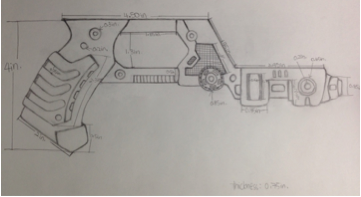
Fig. 3b
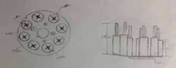
Fig. 3c
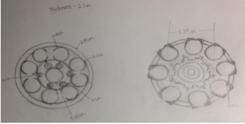
Fig. 3d
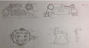
Fig. 3e
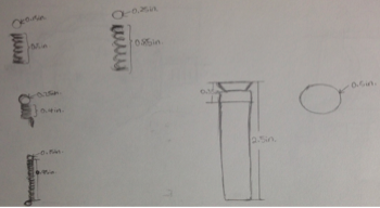
Fig. 3f

Fig. 3g

Fig. 3h
Results: Final Assembly- 23 components
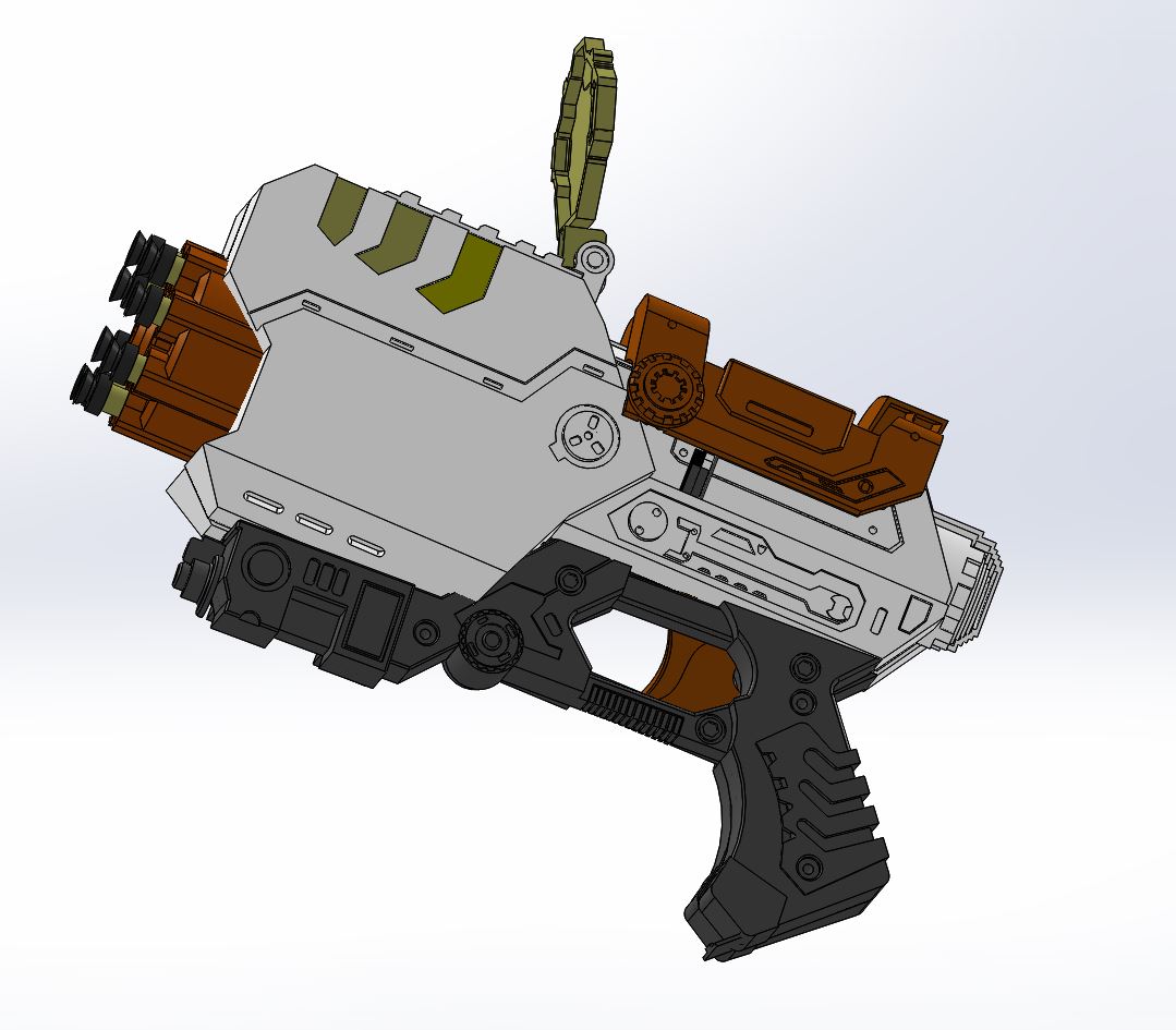
Isometric View
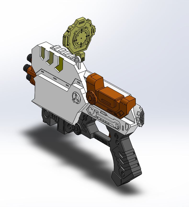
Side View
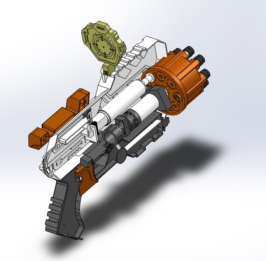
Sectional View
Detail View
Discussion: The final assembly of nerf gun was necessary fully defined but it didn’t combine well. I tried to make it as realistic as possible. I learned that every component must create in order to achieve the assembly results. What makes me struggle the most is mating every components together; it has to match every angle limitations to work for a motion analysis. In fact, the process of creating the components was much easier than doing the assembly. I also learned the difficulty of reversing an existing object to a drafting design and perhaps into a new motion designs.

