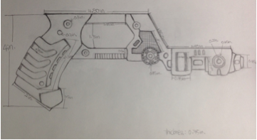
Global Solar Tracker (GST) is the product developed in Cad Plant Layout class of the Industrial Design Department. The objective of this group project is to design and fabricate a tilting mechanism for the solar powered street lights that can tilt the solar panel towards the sun. Our hope is to create a housing component that will hold all the electronics (batteries, motors, micro-controllers, etc.), while keeping the weight of these components from affecting the weight of the panel, and still supporting it during inclement weather.
Challenges: Most solar panels used in solar powered street lights are attached to the post with a fixed angle. As the Earth circles the sun each day, only portions of the sunlight can shine on the solar panel directly. Most of the time, the solar panel is at an angle with the sun. As a result, the solar panel does not take advantage of the solar energy emitted from the sun efficiently.
Benefits of two axis: When solar panels are perpendicular to the sun or the other light source, the intensity of the light is absorbed more completely. However, the dual-axis sun tracker can be even more efficient as it can move horizontally and vertically to capture all the available sunlight. Additionally, the sun tracker keep the solar panels pointed at the sun all the times, and the voltage and power stays higher throughout the day.
Wiring Diagram:
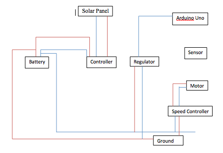
Wiring Diagram
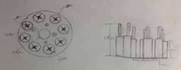
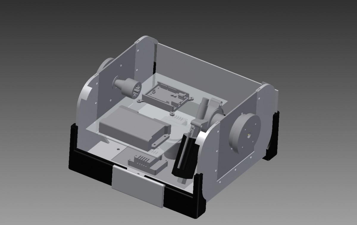
Components: Genesis NP- 18-12B 12V Battery(2), Desno-12V Window Motors (2), Sunforce 8.5m Charge Controller (1), Light Sensors (4), Arduino-Uno (1), TALON SR Speed Controller (2), Ricon 12-5V Regulator (1)
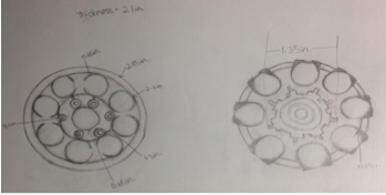
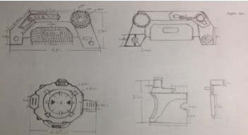
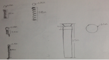
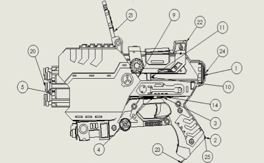
Manufactured/ Designed Parts: Sensor holder, Bearings (3), Shafts (3), Different kinds of spacers(5), Plexi side and top, Rotation Base Plate, Rotation Base, Mount Plate, Logo Side, Motor Mount, Gears (2), Corner Brace (2), Caps (2), Brace Connectors (2), Bottom base Connectors (2), Box Base4 (2), Box Base4 Side, Box Base4 Side Motor, Box Base4 Motor, Bottom Brace (2), Arm Top Plate, Arm Side Plate(4), Arm Ear_Left, Arm Ear_ Right, Arm Bends (2), Arduino Holder
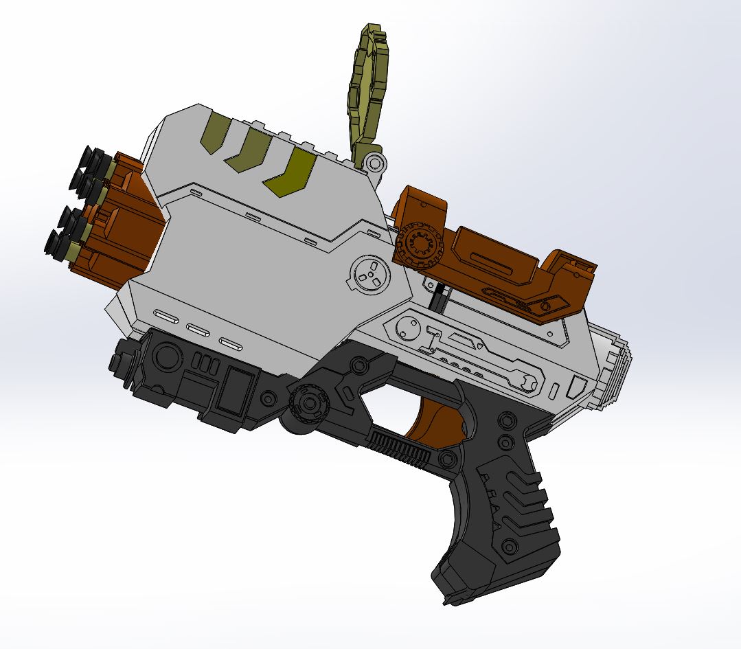
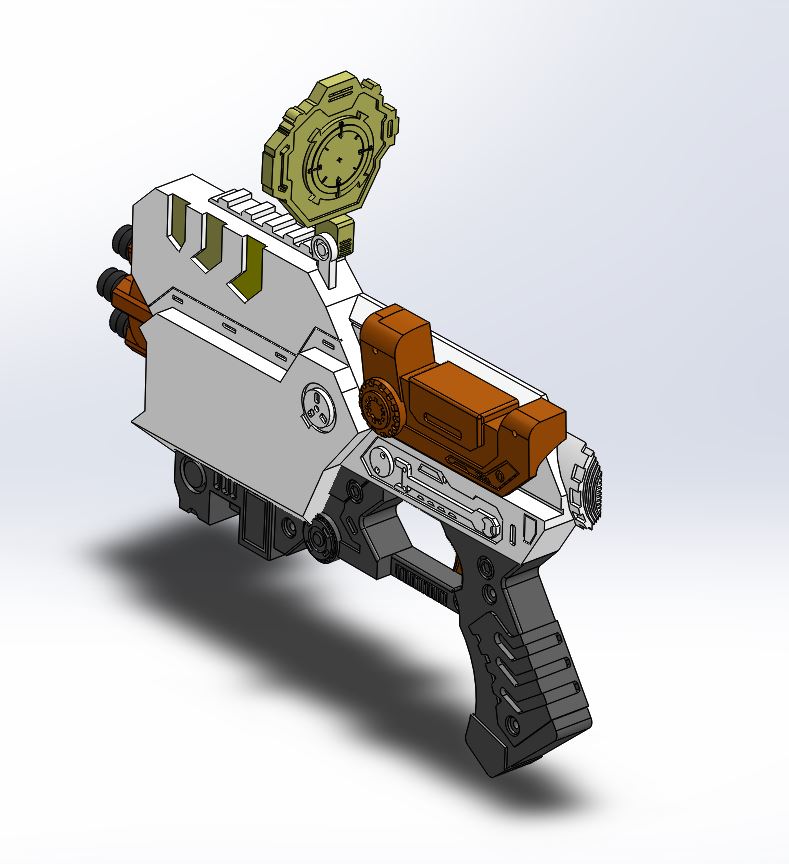
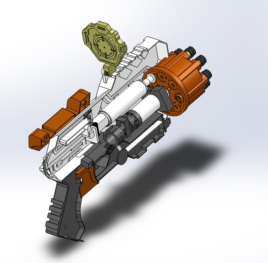
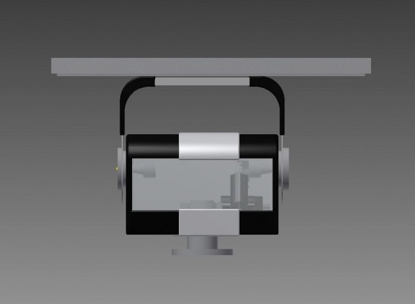
Finished Product:

Isometric View
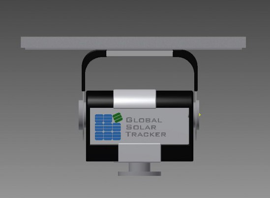
Front View
Back View
Side View
Inner View