Pneumatic Cylinder Geometry

Find below an example of how to determine the position for your pneumatic cylinders in your projects. This is an example I have adapted from the book Mechanical Design for the Stage by Alan Hendrickson. If you are interested in machine design, I highly recommend that book.

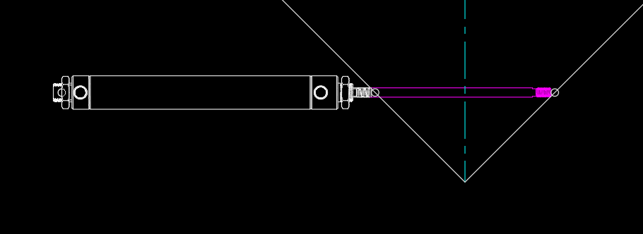
  1. First, draw (or download) your cylinder in your CAD program of choice. I downloaded a sample cylinder from McMaster-Carr (part number 6498K658). I had to adjust the model slightly to show the full size of the part. The retracted position is shown in white, and the extended position is shown in magenta. It will help to make this part into a block for later.
    cylinder in autocad
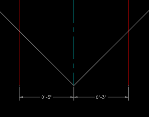
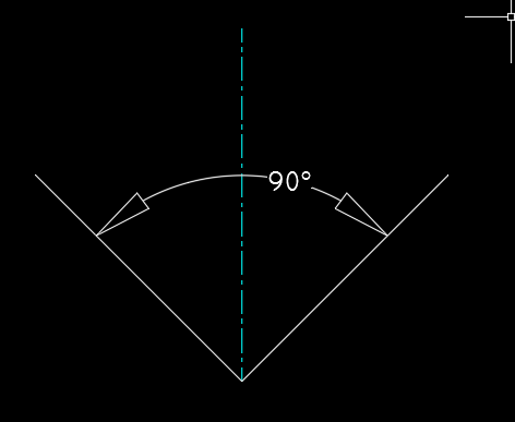
  2. Next, draw a schematic for the motion you are trying to accomplish. In my example, I will open a door 90 degrees, just like the class project. Draw the centerline (blue) and angle of motion (white) as shown below.
    Angle
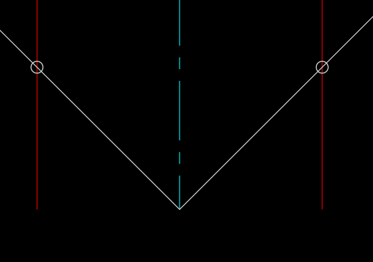
  3. Since the cylinder I chose has a 6″ stroke length, I then offset the center line 3″ to each side. You will need to adjust this distance based on the stroke length of your cylinder.
    offset from center
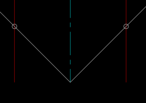
  4. Next I drew a circle at the point where my angle (the white lines) intersect the offsets (the red lines). This will help me accurately position the cylinder in relation to these points.
    points with circles
  5. Now I can add the cylinder block from earlier into the drawing, and turn the whole thing into a new block. The end of the extended rod should touch one circle, and the close position should touch the other circle. The base point of the new block should be the vertex of the angle (where the white lines meet).
    final block
  6. You can use this block to position your cylinder in your model. You can place the base point of the block at the center of the hinge pin in your drawing, then rotate the block until it lines up with the position of the door (or whatever you are moving). Be sure to use OSNAPs for this, so that your model is accurate.
    using block to locate cylinder

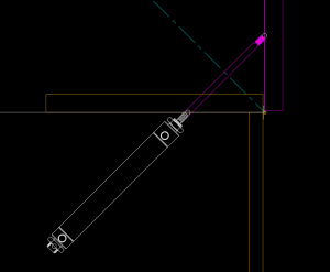
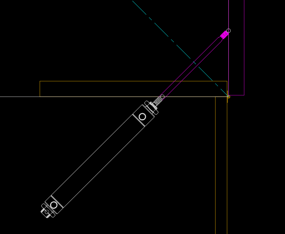
Note that this is only a rough placement to see if your cylinder will fit. To get a more exact placement, you would need to draw all of the connection details for each end of the cylinder.


Posted in Uncategorized | Leave a comment

Extra Credit!

City Tech’s Writing Across the Curriculum team is offering a note-taking workshop on Thursday, October 10th at 1:00pm in Namm 601A. You don’t need to RSVP, you can just drop in. If you attend this workshop, I will replace your lowest quiz grade for the semester with an A+. I highly recommend that you take advantage of this opportunity.

For questions about the workshop, you can contact Rebecca Mazumdar  (mazumdar@citytech.cuny.edu) or Samar (ElHitti selhitti@citytech.cuny.edu)

Posted in Uncategorized | Leave a comment

Makeup Quizzes

As we discussed in class, if you would like to improve your grade on a quiz, you can. Here’s what you need to do:

Once you get back a graded quiz, you have one week to review the material and submit a paper showing that you have mastered the content of the quiz. Your paper will need to be typed, double-spaced, and at least one page long. Explain the material that you got wrong on the quiz, and be sure to cite the source where you found the answer. In addition, write at least a paragraph about how the information your learned will be useful in the future: how will you use the information in this class, in your work, in your life?

Posted in Uncategorized | Leave a comment

507 Mechanical Movements

Here is the site I showed you in class today: http://507movements.com/

I have the book this is based on, and I like to keep it by my desk and leaf through it when I’m working on a machine design. Some of these simple mechanical connections are so clever, it is inspiring to browse through all the different arrangements of parts that people have come up with.

I think it really helps to have seen all of these machines just to have in the back of my mind when I think about a problem. I never would have come up with these designs, but once I’ve seen them, I can imagine lots of ways to use them in my work.


Posted in Uncategorized | Leave a comment

Geometry Review

Tomorrow we start with pneumatic actuators and air power tomorrow. To be prepared to discuss pressures, actuator sizes, and required forces, we need to be comfortable with calculating the area of various shapes. For a quick geometry review, check out https://www.mathsisfun.com/geometry/area.html

Posted in Uncategorized | Leave a comment

Homework #1

The machine I picked was The Dallas Stars’ lighting star. The lighting star is used for the entrance of the Dallas Stars, a hockey team in Dallas, Texas. It’s a huge star that is placed over the entrance of where the hockey players enter from the locker room to the rink. There are lights inside the piece that blink or glow when the players enter the ice. It was used greatly during the Stanley Cup playoffs when the Stars had their home games and there’s a video (Link will be on the bottom) of how it’s lowered and lights up. I think it’s very cool because of the many lights inside, while it does show a lot of things like the rigging system, LED and moving lights inside the actual star and it looks like the Star is made of trusses. I watch the Dallas Stars and their playoff intro is very good and popular, of course I’ve watched it and I loved it. The simple machines that were used in this were Pullys. The Pullys were used to lower and raise the Star up and down.

Posted in Uncategorized | 1 Comment

Simple machines in roller coasters

Typically at the beginning of a roller coaster track there is a closed pulley system. Similar to a bike chain the system continuously runs through the pulleys on each end.  There is one pulley at both the top and bottom of the portion of the track that climbs. During this portion the pulley is helping the coaster cars build momentum so the cars can run through the rest of the track. Because of the momentum in the coaster after the pulley systems drop  there is a lot of force that needs bracing and brakes in order to stop at the end of the course so there are different versions for stopping the coaster. There are some that are designed or programmed to stop at the end of the course, but there are also ones that have clamps or breaks like on a bike tire.

https://prezi.com/m/cuiw-s7g-we_/the-engineering-behind-roller-coasters/

I thought the systems of simple machines in a roller coaster was a cool concept for simple machines because it’s simple in concept but extremely impactful for the entirety of the ride. Also I love roller coasters.

Posted in Uncategorized | 1 Comment

HW#1- Machine Research- C CLamp

C Clamp

C- clamp device typically used to hold a wood or metal work tool, and often used in, but are not limited to, carpentry and welding. Often believed that these clamps are called “C” clamps because of their C-shaped frame, or also often called C-clamps or G-clamps because including the screw part they are shaped like an uppercase letter g, but in fact they were originally called a carriage makers clamp, or Carriage Clamp.

G-clamp or C-Clamp is used by means of turning the screw through the bottom of the frame until the desired state of pressure or release is reached.

The most interesting function of this device is holding 2 pieces of wood at the same time turn the screw to force them to be aligned or parallel.

It is my favorite tool because it helps so much in the process of building and load in. It is necessary during both processes.

Posted in Uncategorized | 1 Comment

HW#1

The Crane works by bringing heavy material to a designated area.It works by 3 simple machines.Those 3 simple machines are a lever, pulley and a wheel and axle but just in bigger pieces. The 2 that are going to be explained is the wheel and axle and the pulley which are the ones that pick up and drop off the load.I found out information on a youtube video to see a visual representation and read about it on an internet page that broke into pieces explaining every different simple machine on the crane.In my opinion I saw it really cool because as you see a crane in the street and see it pick up real heavy material how can it just pick it up with a single pulley an be safe.

The lever is what makes the pulley come down and pick up the load so it will get longer as the pulley comes down.

The pulley is a fixed pulley with a rope and a wheel and axle.It changes the direction of force and the rope gets lowered as it is getting ready to lift load then the rope comes up as it is lifting the load.


https://prezi.com/8vhlkm7vi2hs/simple-machine-crane/

Posted in Uncategorized | 1 Comment

HW #1 – Roosevelt Rozon

Roosevelt Rozon

The first machine that came to mind was the “Boneshakers” automaton. Automaton is a mechanical device that is made to imitate the movements of a human being. It uses a series of simple machines in order to follow a set sequence of movements. It requires no software or electricity for this to happen. Automatons can be dated back to medieval times.

https://themadmuseum.co.uk/history-of-automata/


The “Boneshakers” automaton tells a story of three skeletons riding on a bike being chased by a dog. The skeletons are pedaling while they move away from the bike to look back at the dog chasing them. As seen in the video, the simple machines used in this are wheel and axles using gears, pulleys, and a lever. The wheel and axles mechanism is used to turn the wheels on the bikes as well as propel wooden wedges that provide the movements for the running dog. The pulleys are also moved using the wheel and axles. 


This stood out to me due to how it is constructed to follow the exact same sequence with every rotation. All these movements are accomplished with the use of simple machines. It’s like the very basis for robots without the use of electricity or computer programming.

Posted in Uncategorized | 1 Comment