
Develop Stud plan details based on your groups wall assembly components. Complete one thorough plan of this type. You may complete additional stud plans for extra credit.
Considerations:
align your studs at the exterior face of your 8 inch concrete foundation wall
start with one layout point for your 24″ [or 16”] oc (on center)
at windows indicate your studs are cripples by hatching them and using a light line weight
utilize your ground-floor as a base drawing (or above)
Lecture notes: https://openlab.citytech.cuny.edu/bt2-2024s/files/2022/03/Stud22s.pdf
Submittal:
submit BOTH the pdf and the dwg files.
boards, 34×22 in PDF format (three boards minimum)
DWG files and xrefs (etransmit)
combine the individual pdf pages into 1 file.
Name files using the following naming convention:
All digital files must be submitted in the following format:
Course number semester/year_Professor initials _Project Name_ Student Name (file number)
For example: ARCH2331_ SP24_AA_A01Logo_BFuller (01)
files not conforming to department standards may be graded.
Line placement example (in the metric):
- group 1 wall assembly is 450 mm thick, extend the wall to match 450 mm
- locate exterior edge of stud distance from exterior finish (88 mm in this example)
- that would be the line of your concrete slab edge or foundation wall
- the Interior edge will be at 200 mm
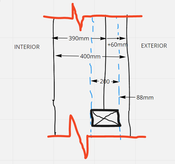
- align your studs at the exterior face of your 200mm concrete foundation wall
- start with one layout point for your 600 mm oc (on center)
- at windows indicate your studs are cripples by hatching them and using a light dashed line.
- utilize your ground-floor as a base drawing (consider XREF thing your plan into your stud plan)

