Here are the pictures of what we discussed during summer time.


-
Recent Posts
Recent Comments
- solarrs on Discussion about Parameter – Image on Board
Archives
Categories
Meta

Here are the pictures of what we discussed during summer time.
Posted in Uncategorized
For one or two weeks, we have talked about how many frames as we view in our own perspectives. For example, when Masa uses 24 images ( frame per second ) displaying on monitor, we can view only 1 image at a time when the RPM is between 475 and 525. For 18 fps, the RPM is around 400. and we view in our own perspectives as 1 to 1.5 images. So, in order for us to view as one image, it has been quite a challenge for us to consider ahead because there are many issues such as rotating in a rough surface, too much vibration, and so on.
Besides that, our research has come some topics for following;
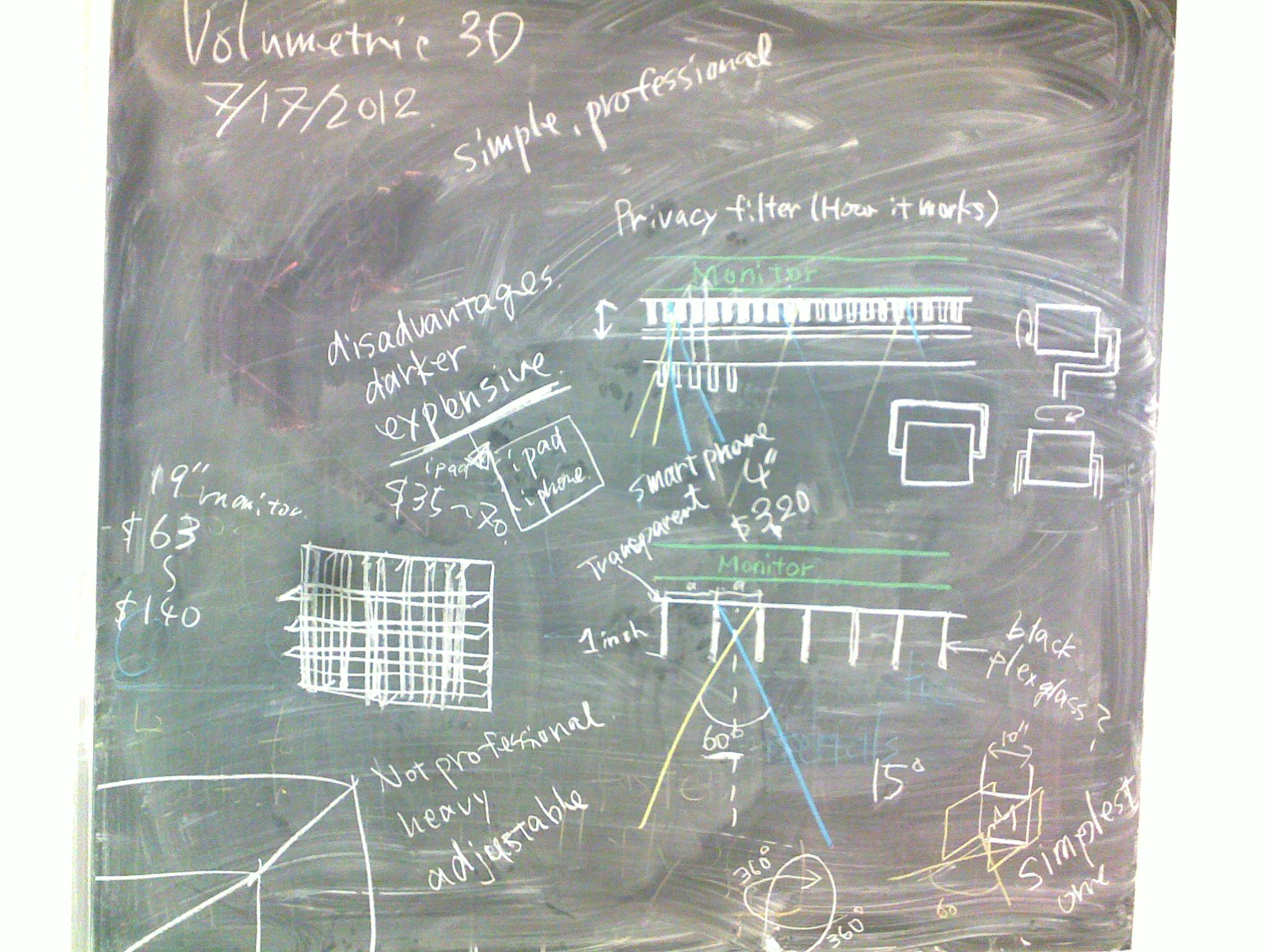
1. Filtering – we need filtration to get individual aspect, by making cardboard ( 30 or 45 degree ).
2. The animation for 24 fps and 18 fps background has to be black because we can see it clearly, especially when we want to see the picture.
3. If there is a problem about vibration, then we might need the second tire to support and make it stabilized. ( especially when we put the higher RPM )
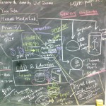
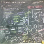
Here is the picture that we came up some brainstorms.

Posted in Uncategorized
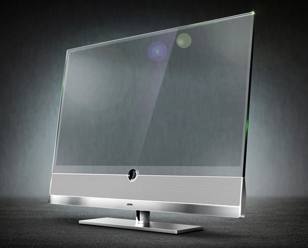
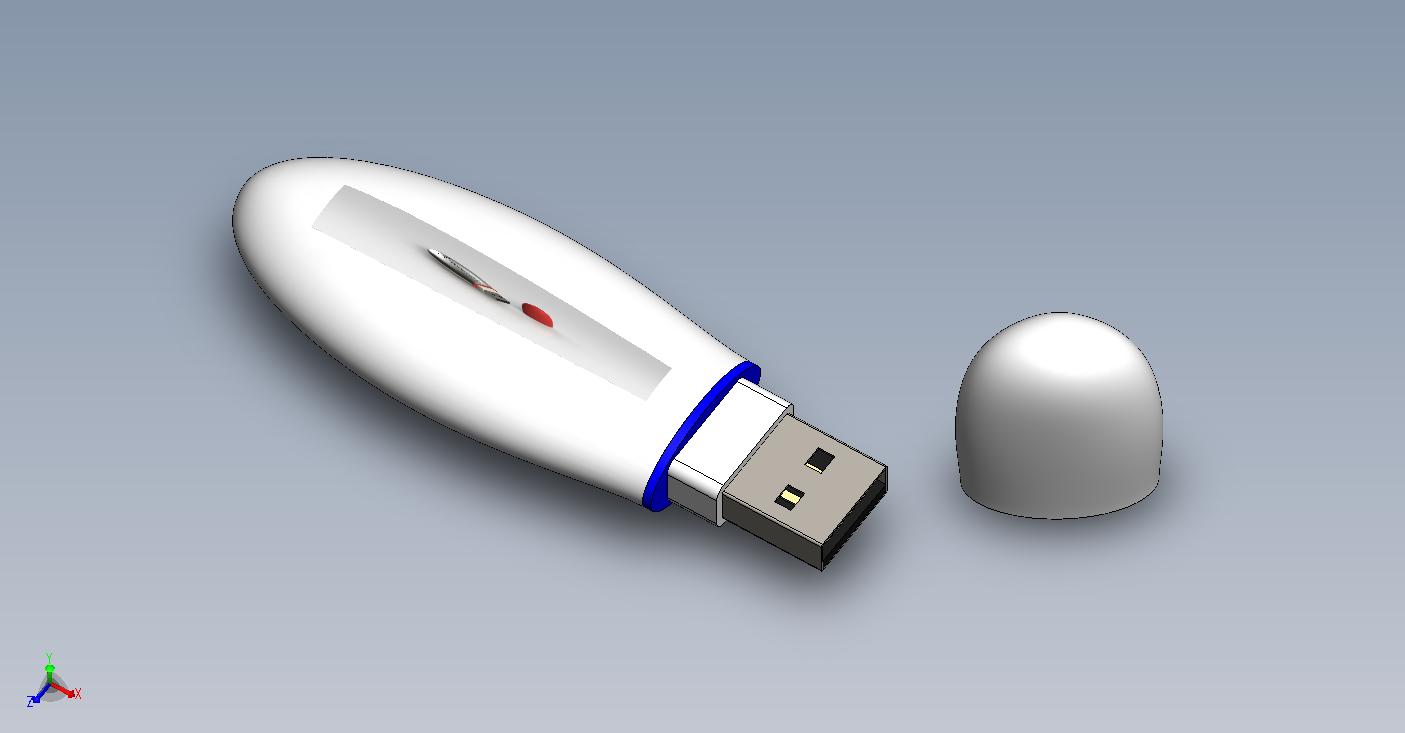
Here is the concept for 3D display monitor. The picture is from Loewe Invisio.
Here is the website : http://www.yankodesign.com/2011/02/03/look-carefully-it%E2%80%99s-a-transparent-tv/
Posted in Uncategorized
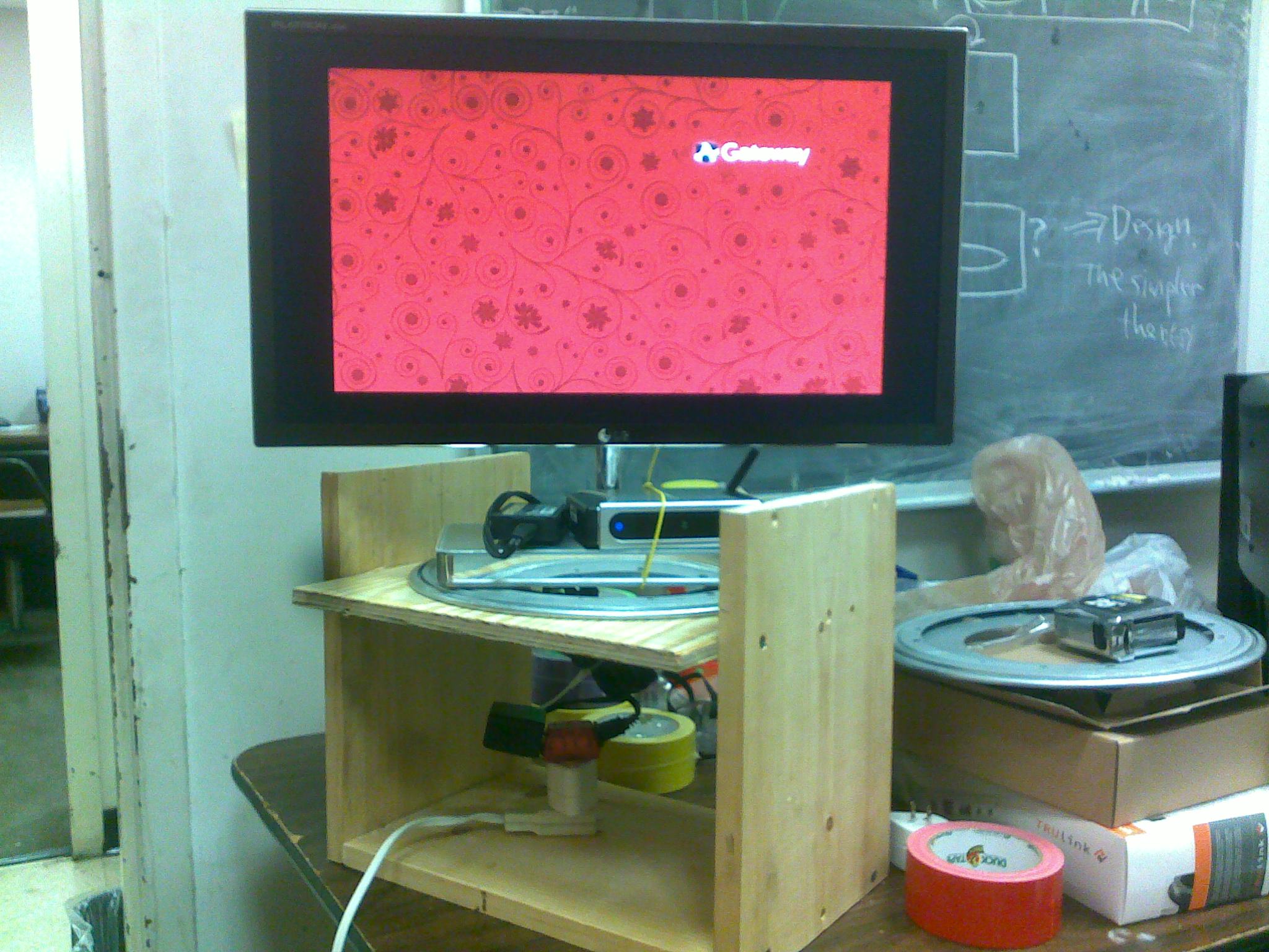
As we can see, the more that we modify, the more idea would be it. Today, we installed motor and tire along with table. Although we tested several times, we have found that we need to re-adjust
1. Clearance for rotating and tire position so that it reduces wobbling.
2. We need to re-adjust shaft to secure the tire more stable.


This is the prototype 1 for widening top layer of wood. We are expecting to attach a motor with a small toy of tire, rotating under top layer of wood. Here are the samples.


First, we put the double layers to see the different perspectives. Second, we measure the difference of degrees to test out whether from our front view or different angle is shown. From our front view, we can see the picture clearly. When the angles adjust between 35 to 40 degrees, the views change from mid dark to completely dark.
ZERO DEGREE’S VIEW 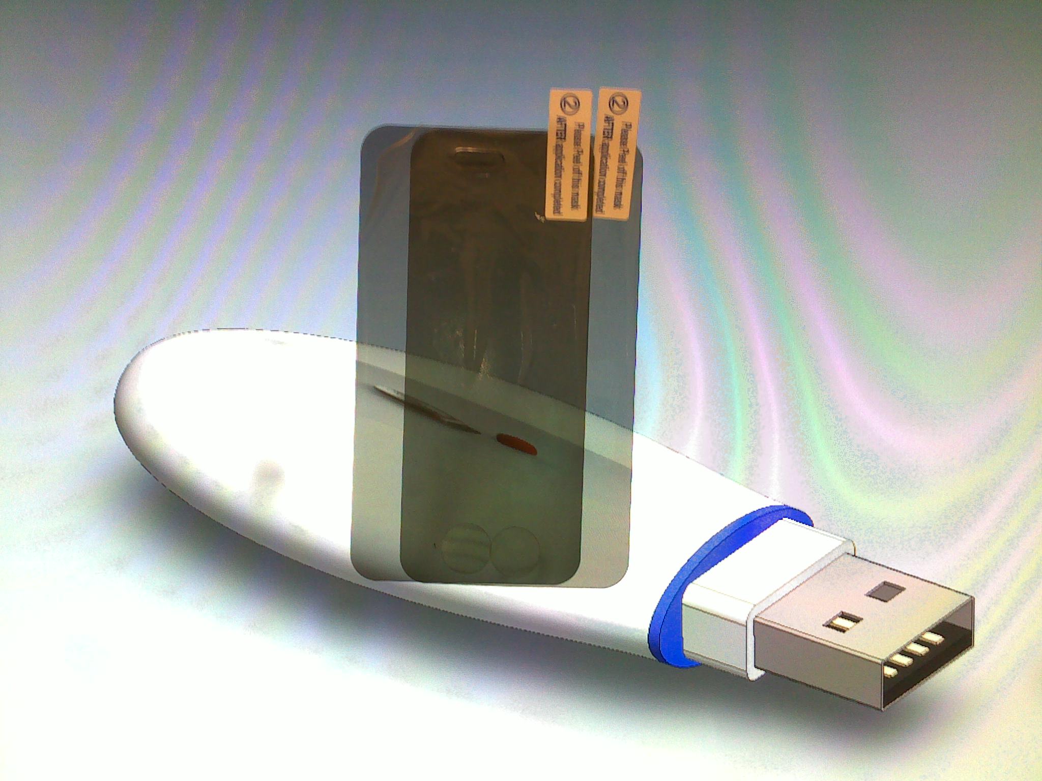
15 TO 25 DEGREES’ VIEW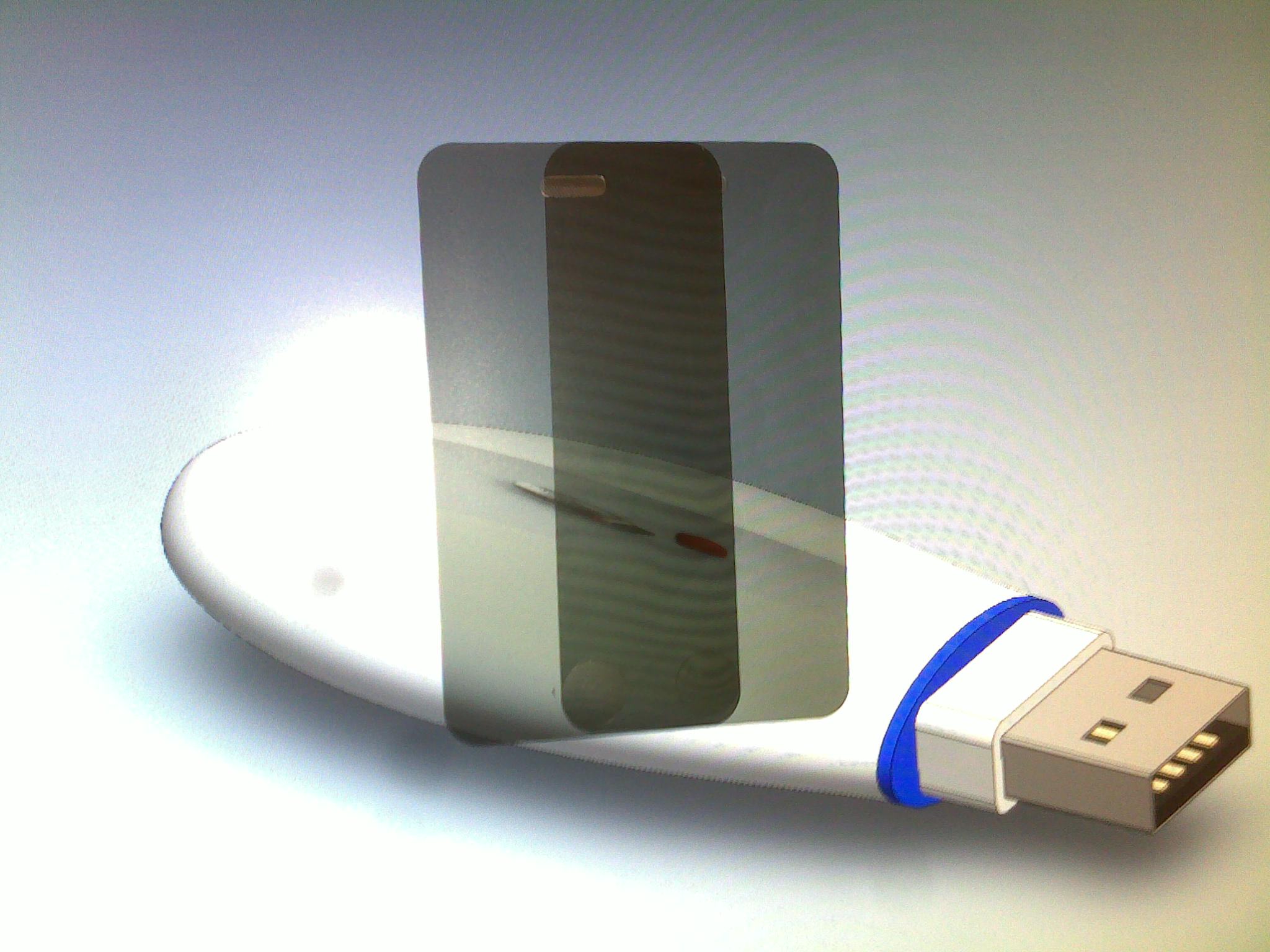
35-40 DEGREES’ VIEW
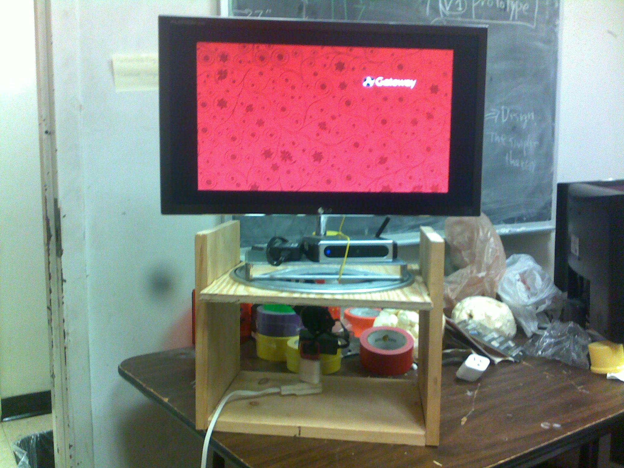
Yesterday, we did some testing and it was getting better. However, we need to improve the table and wiring connection so that when the monitor rotates, it doesn’t hit wires. Here are the pictures that we had yesterday.
Posted in Uncategorized
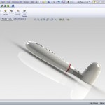
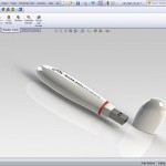
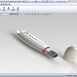
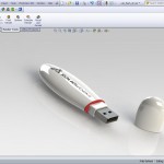
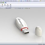
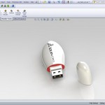
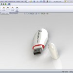
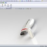
Here is the sample e-drawing without using SolidWork to open the file. It’s very beautiful and interesting.
Here are the pictures of what we have been through. 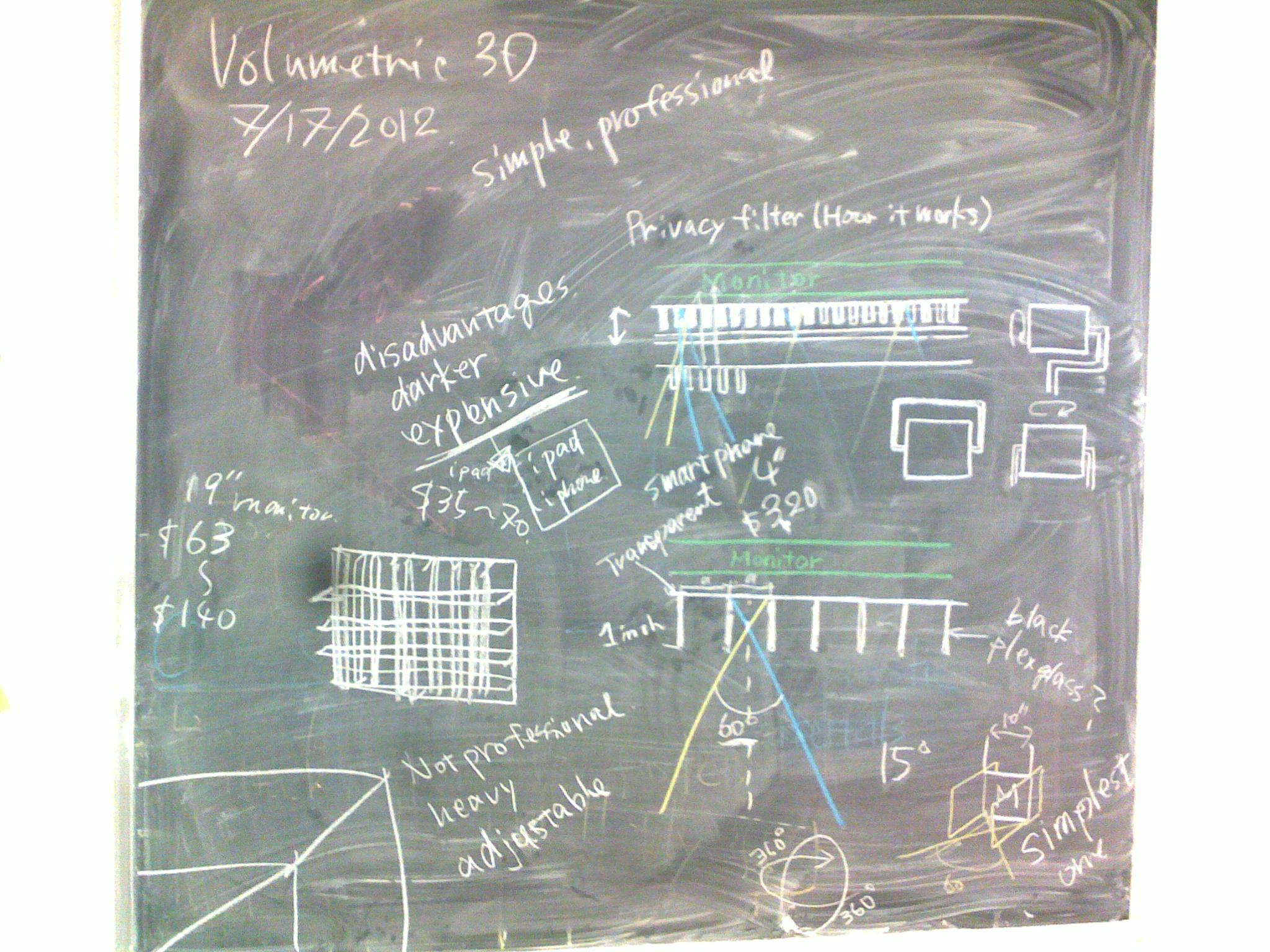
Steps need to be considered
1. Use software to design a project using Solidwork
2. Need materials for turn-table system – through Home Depot
3. Need Filter Protection – 15, 30, or 60 degree.
4. We have already the motor for rotation
5. Need Monitor (LED) from 19″ to 22″.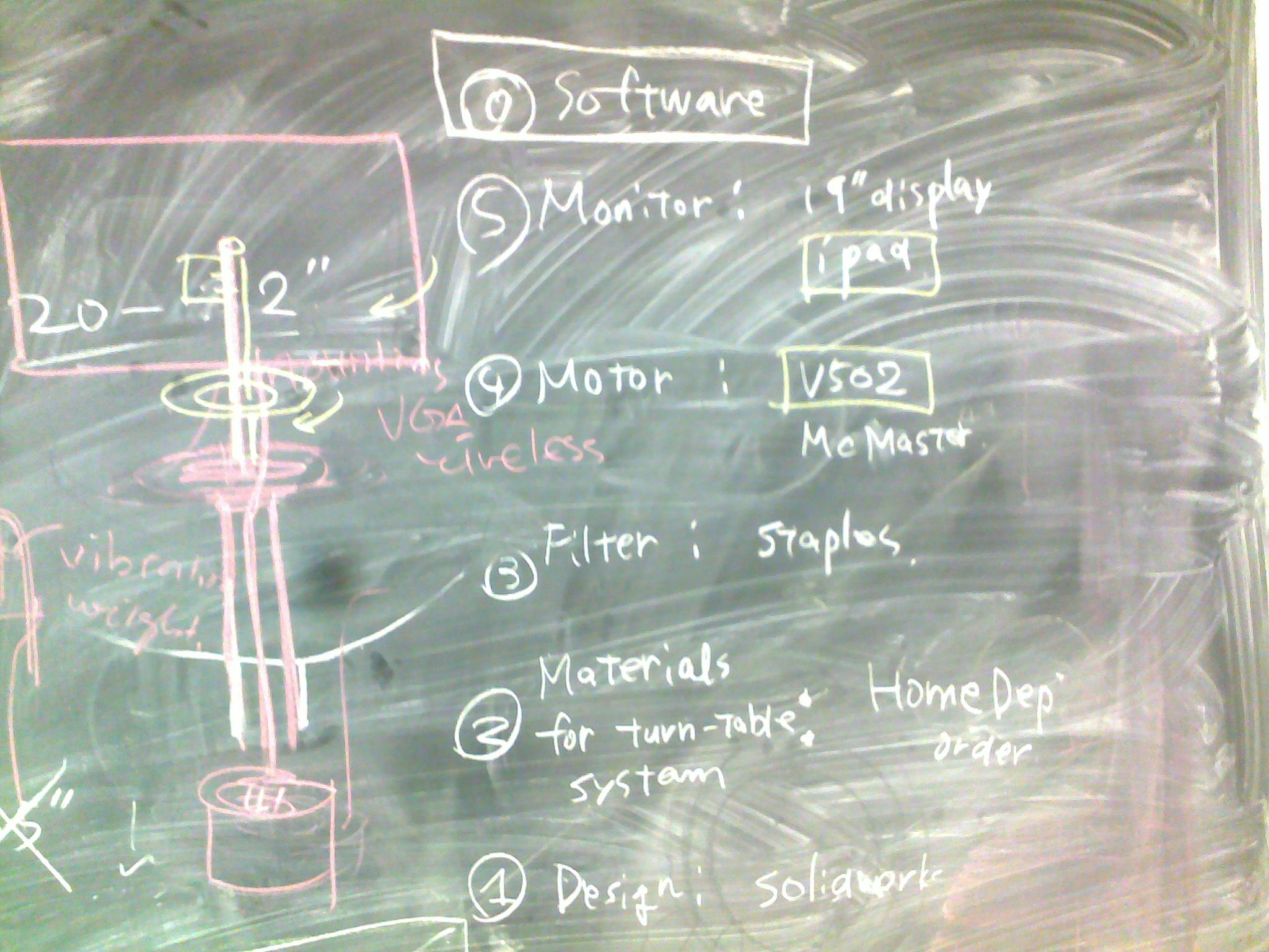
Here is the design I came off :
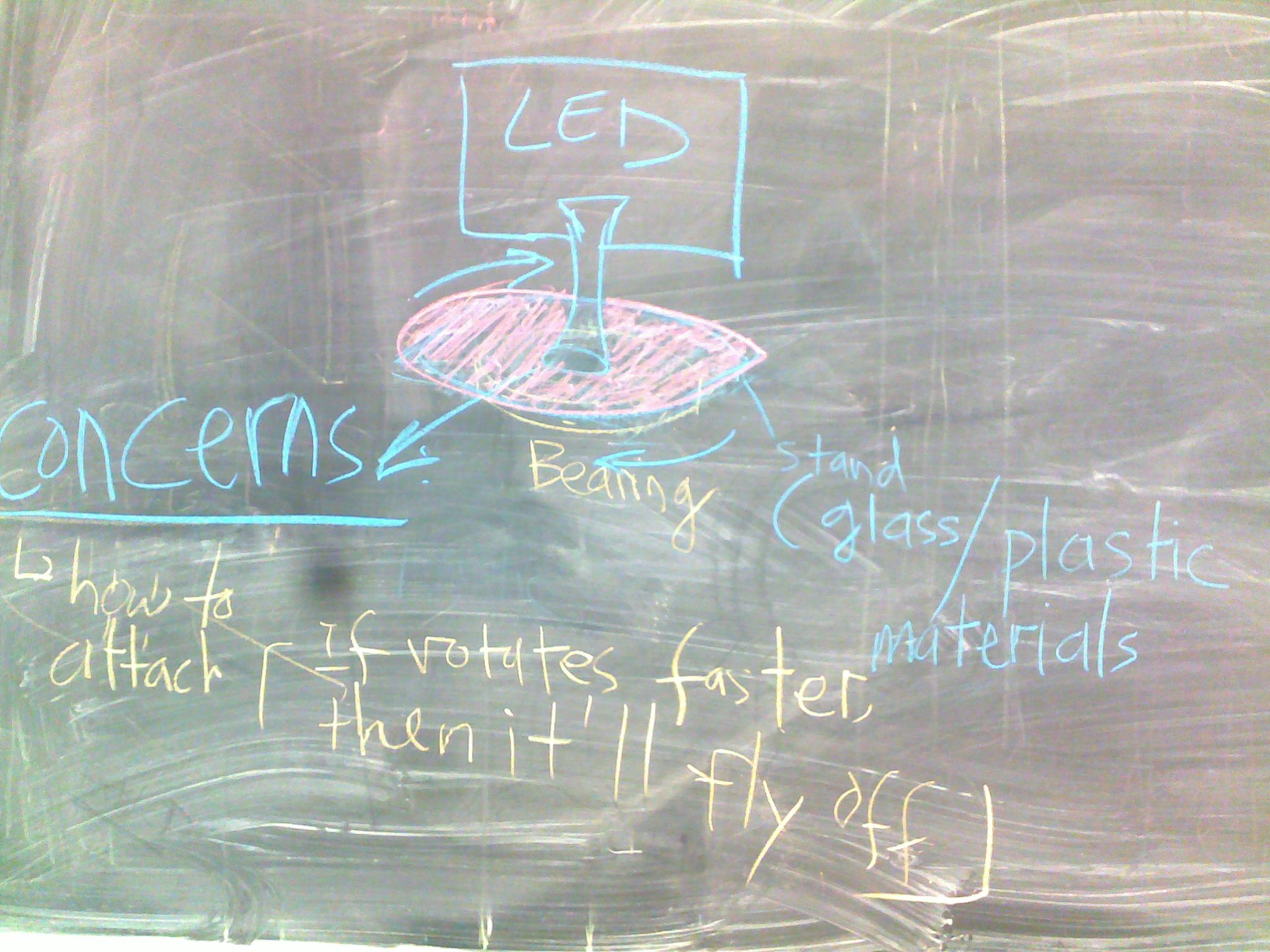
Note: We have the LED with stand and a piece of glass/plastic circle to place under the bearing part. However, the concern that I would bring is how we are going to attach the place between the standing ( mounting part ) and the glass/plastic circle. If it rotates faster, then it will fly off.
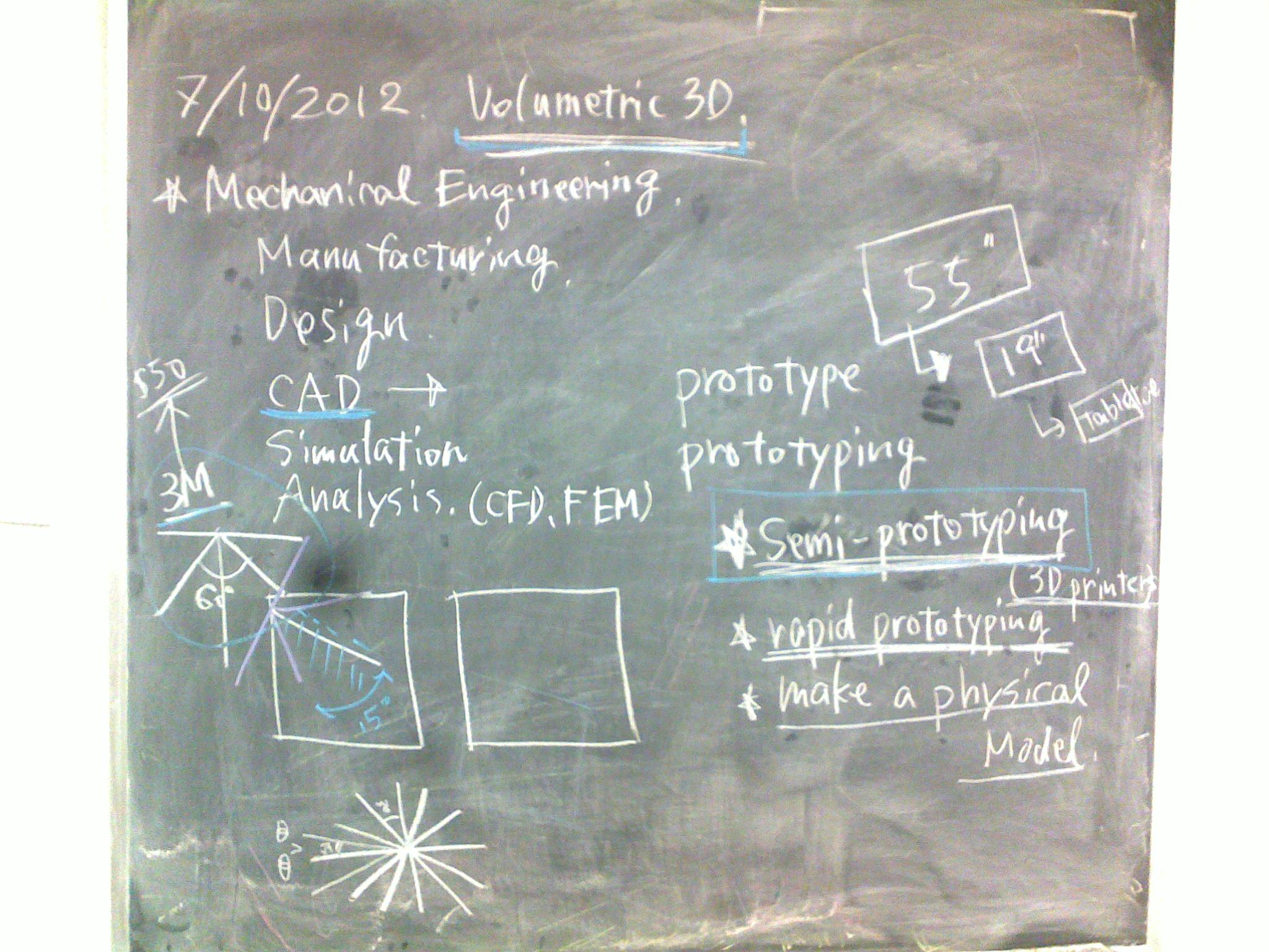
Today, Professor discussed about 3M screen protector. It refers that we can use the screen protector to illustrate that there are some certain degrees we can look at, not the whole 360 degree. Also, there are some changes on our project.
– Mechanical Engineering
– Manufacturing
– Design
– CAD – computer application
– Simulation
– Analysis ( CFI, Pro F.E. )
Steps have changed
1. Semi-prototyping – ( progress on trying to assemble prototype )
2. Rapid prototyping (3D printer) – Room 508
3. Make a physical model ( real prototype model )
4. Since the 55″ monitor is too big and concerned about weight issue, we have decided that we need to do some experiments first. Then, we can determine later.
Here is the picture on what we discussed today.
Here are the few steps we need to consider.
Stage 1 Mechanical Design
– we need to layout a spec. detail on what we need to construct after we finalize what we need to purchase. It will take more time to construct and assemble.
Stage 2 Software Design
– we want to create an 3D design display on our project. 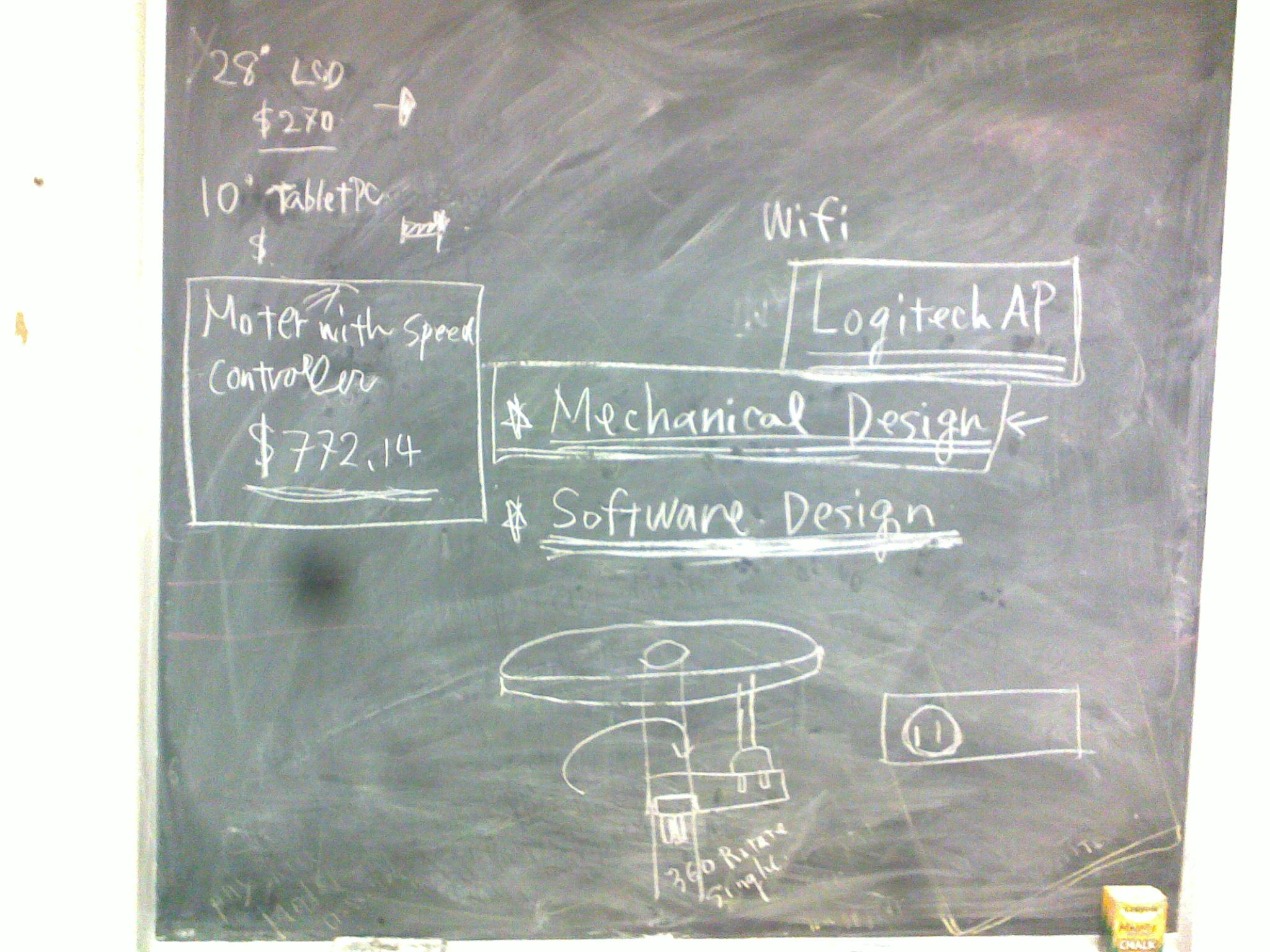
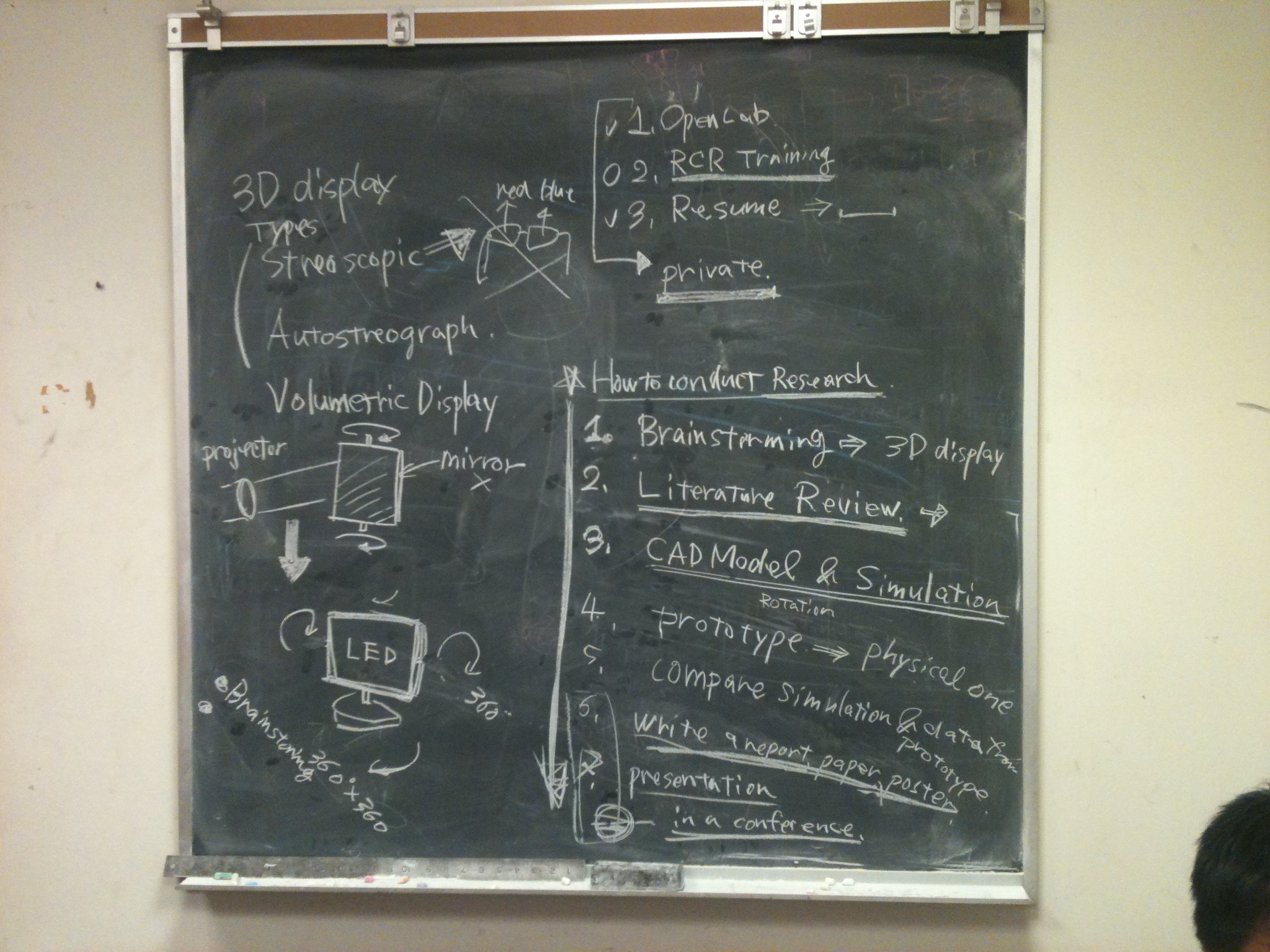
1. How to conduct a research
2. CITI RCR training needs to finish.
3. Continual brainstorming.
4. 
The OpenLab is an open-source, digital platform designed to support teaching and learning at City Tech (New York City College of Technology), and to promote student and faculty engagement in the intellectual and social life of the college community.

