Outline
- Inductor/Capacitor
- Real/ideal
- Reactance
- Q – factor
- Resonant circuits and circuit Q
- Maximum power transfer
- Matching
- L-, T-, π-networks
Inductor
Ideal Real

Ideal and real circuit models for an inductor.
Capacitor
Ideal Real
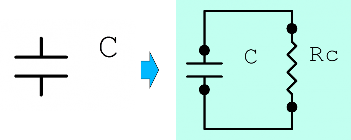
Ideal and real circuit models for a capacitor.
Reactance
Recall the formulas for the reactance of an inductor (


")
Reactance is a description of how components react to changes in voltage or current.
Quality Factor (Q)
- Q-factor: A ratio

- Can be found from the physical characteristics of any component.
- Depends on how the resistive element is modeled, i.e. in series or in parallel with the ideal component.

Resonant Circuits
RLC tuned circuits

Series Resonant Circuit

Parallel Resonant Circuit
- Center resonant frequency:
- The quality of a resonant circuit is also a measure of selectivity, i.e. how well the tank circuit can select a specific frequency while filtering out the others.


Not all ‘Q’s are the same!
- Component Q is NOT the same as circuit Q!
- Component Q DOES AFFECT circuit Q!
Using Q to change the model

Converting serial/parallel models to parallel/serial models.
R_s")
")
Note that since we’re manipulating the same component, 
Only the model is changing, not the component.
Insertion Loss
- Inductors and capacitors are not ideal components!
- They’re resistance acts as an extra load in the circuit, not only causing changes in circuit Q, but also losses in the transfer of power.
Insertion loss example
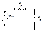
Original circuit before insertion loss.

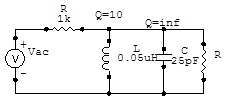
Insertion loss calculated after adding reactive components.

Impedance Matching
What is matching?
- Values for source and load to guarantee maximum transfer of power!
How does it work with complex signals?
- Work with complex conjugates!
L-networks
- They look like an ‘L,’ though it may be upside-down.
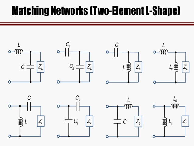
Courtesy of Simen Li, Attribution 4.0 International
- IT is possible to find the values of L & C analytically, but why do that when we can simplify things and work with Q.

- Based on the previous equations it appears as though we are limited in some way.
- Notice that for real values of Q,
- Furthermore, once we know what the resistances are the value of Q is fixed.
- What if we wanted to have control over what Q is in the circuit?
- Even more so, why would we even want that?

- If we can choose our Q, then which is the best option: high selectivity or high bandwidth?
- It depends on the application.
- Furthermore, it is possible to have multiple networks cascaded together. (Reference 1, Reference 2, Reference 3)
The slides for this lesson may be found here.

This work is licensed under a Creative Commons Attribution-ShareAlike 4.0 International License.
Tags: Insertion Loss, Matching, networks, Q, quality factor

