Matching Networks
Why do we match?
Matching is used to achieve maximum power transfer from a source to a load.
Why use a resistive, or passive, attenuator?
Resistors are used to specifically attenuate a signal to a lower signal strength. Though we could achieve the same objective with reactive components such as conductors and capacitors, those components have impedances that change with the frequency of the incoming signal. Using passive components we can guarantee a fixed attenuation irrespective of whether the signal is a DC or an AC signal.
Why do we need a lower signal strength?
Certain pieces of test and measurement equipment cannot read high value signals. For example, the maximum voltage some digital multi-meters may accept is only 100 V. If you want to measure that voltage with an instrument that can only measure at most 10 V, you’d think that you have no choice but to go out and buy a meter that can handle that. However, you can save yourself a lot of money by using an attenuator that is matched appropriately to the meter that you’re using and the source that you’re measuring.
Equivalently, if you want to test the sensitivity of a piece of equipment, trying to generate a very weak signal would be just as complicated as generating a strong signal. Instead of using a piece of complicated equipment with multiple modes, an attenuator may be used in series with the signal generator to reduce the signal strength to almost any arbitrary value.
In fact, you’ve been using attenuator networks in one form or another for quite a while without even realizing it. The volume control on all audio devices that you use to change the intensity of sound is nothing more than an attenuator. You probably have heard some people refer to it as a variable resistor, rheostat, or potentiometer, but in it’s functional form it acts as an attenuator. When you change the volume to a higher or lower level sound, you are essentially changing the resistive value of an attenuator network, even if it’s just one variable resistor.
Configurations
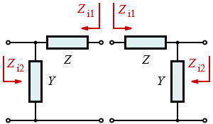
Resistive pads come in all forms or configurations. The basic one is known as an L-pad, as seen here.
One thing to notice is that the L-pad is nothing more than a voltage divider, but with specific constraints placed on it. The constraint is limited only to the amount of attenuation that we want to achieve. Also note that the design of the resistive values of the L-pad are made based on the assumption that both source and load are already matched, i.e. have identical resistive values.
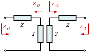
The next most common configurations are the T-network, bridged T-network, and the π-network (also written as Pi-network).
Each one is actually a construction of placing multiple L-pad networks together. For example, a T-network is nothing more than the connection of two L-networks head-to-head and a Pi-network is achieved by connecting two L-networks back-to-back.
An attenuator for every occasion
Attenuators are classified in terms of the dB attenuation that they provide. You can create an attenuator that provides any arbitrary attenuation, assuming that it’s feasible. There are plenty of online calculators that let you verify this.
Does this mean that every time a different value of attenuation is necessary a new attenuator must be designed? Not quite. Fortunately, you can create fixed value attenuators and switch between them, thereby providing you with an almost limitless variety of combinations of attenuation similar to a resistive decade box or capacitive decade box.

This work is licensed under a Creative Commons Attribution-ShareAlike 4.0 International License.


