Assignment 2 Introduction
We create robotic motion in RobotStudio by adding robtargets to paths as motion instructions.
A typical motion instruction looks like this:
MoveL pDwg_10,v50,z1,tPen\WObj:=WobjPad;
Where:
- “Move L” defines the type of motion: a linear move. This means that the robot will move the TCP in a straight line from its previous robtarget to the robtarget indicated in the argument. The other common motion type is a “Move J” or joint move. This motion type allows the robot to move with relative freedom in space. Typically you will use “Move J” in the air and “Move L” at the workpiece.
- “pDwg_10” defines the destination robtarget. Robtarget names typically start with a lowercase “p” for “point” and are appended with a number which indicates its sequence within a path. “10” would indicate that this is the first robtarget in the path as robtargets are typically incremented by 10 which allows for up to 9 intermediate robtargets if necessary for good robotic motion.
- “v50” defines the velocity of the motion in mm/s. For further information on speeddata click here.
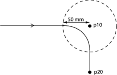
- “z1” defines zonedata in mm of diameter of circle around the robtarget centerpoint. Zonedata determines whether a robtarget is a stop point or a fly-by point. A stop point would use zonedata of “z0” or “zfine” if a momentary pause is required. A fly-by point uses larger zonedata figures to allow the TCP to travel in a parabola defined by the zone circle diameter and the tangencies of the previous and next robtargets. For further information on zonedata click here.
- “tPen” indicates our active tool so that the robot’s joints can be offset by the TCP vector to ensure accurate tool contact with, and motion relative to, the robtarget.
- “WObj:=WobjPad” indicates that we are operating within the workobject (or relative coordinate system) we’ve defined for our workpiece, in this instance a pad of paper.
Assignment 2 Part A
Begin the assignment by defining the following robtargets:
- 4 corners of a quadrilateral as four robtargets as “pQuad_10” – “pQuad_40”
- A starting position as “pStart”
- A shared approach and depart position as “pApproach”
Create a path called “rQuad” using joint motion in the air and linear motion at the workpiece. Use a speed of “v50” and a zone of “z0” and set the active tool to “tPen” and the active workobject to “WobjPad.” Your RAPID code should look something like this, with a declaration, a main routine, and subroutines (for more information on RAPID program setup and flow click here:
MODULE Module1

 CONST robtarget pStart:=[[325.000415457,500.000150348,367.139833629],[0.000000649,0,1,0.000000082],[0,0,0,0],[9E9,9E9,9E9,9E9,9E9,9E9]];
 CONST robtarget pApproach:=[[538.194158179,196.023629276,130.108793505],[0.000000119,-0.000000507,1,-0.000000044],[-1,-1,-1,0],[9E9,9E9,9E9,9E9,9E9,9E9]];
 CONST robtarget pQuad10:=[[538.193878267,196.023732755,-0.000478914],[-0.0000003,-0.000000507,1,0.000000111],[-1,0,-1,0],[9E9,9E9,9E9,9E9,9E9,9E9]];
 CONST robtarget pQuad20:=[[368.210661979,94.758937773,-0.000718556],[-0.00000068,-0.000000477,1,0.000000476],[-1,0,-1,0],[9E9,9E9,9E9,9E9,9E9,9E9]];
 CONST robtarget pQuad30:=[[271.205165269,294.21958357,-0.00080897],[-0.000000732,-0.000000526,1,0.000000445],[-1,0,-1,0],[9E9,9E9,9E9,9E9,9E9,9E9]];
 CONST robtarget pQuad40:=[[411.63553811,337.497516288,-0.000825862],[-0.000000767,-0.000000579,1,0.000000427],[-1,0,-1,0],[9E9,9E9,9E9,9E9,9E9,9E9]];

 PROC main()
 rQuad;
 RETURN;
 ENDPROC

 PROC rQuad()
 MoveJ pStart,v50,z0,tPen\WObj:=WobjPad;
 MoveJ pApproach,v50,z0,tPen\WObj:=WobjPad;
 MoveL pQuad10,v50,z0,tPen\WObj:=WobjPad;
 MoveL pQuad20,v50,z0,tPen\WObj:=WobjPad;
 MoveL pQuad30,v50,z0,tPen\WObj:=WobjPad;
 MoveL pQuad40,v50,z0,tPen\WObj:=WobjPad;
 MoveL pQuad10,v50,z0,tPen\WObj:=WobjPad;
 MoveL pApproach,v50,z0,tPen\WObj:=WobjPad;
 MoveJ pStart,v50,z0,tPen\WObj:=WobjPad;
 RETURN;
 ENDPROC

ENDMODULE
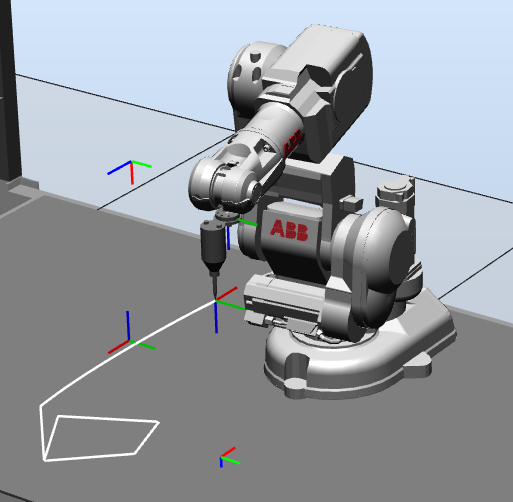
The resulting motion should look something like this:
Next, duplicate the series of moves at the workpiece and increment the zone data. The RAPID within rQuad() should look something like this:
PROC rQuad()
 MoveJ pStart,v50,z0,tPen\WObj:=WobjPad;
 MoveJ pApproach,v50,z0,tPen\WObj:=WobjPad;

 MoveL pQuad10,v50,z0,tPen\WObj:=WobjPad;
 MoveL pQuad20,v50,z0,tPen\WObj:=WobjPad;
 MoveL pQuad30,v50,z0,tPen\WObj:=WobjPad;
 MoveL pQuad40,v50,z0,tPen\WObj:=WobjPad;
 MoveL pQuad10,v50,z0,tPen\WObj:=WobjPad;

 MoveL pQuad20,v50,z10,tPen\WObj:=WobjPad;
 MoveL pQuad30,v50,z10,tPen\WObj:=WobjPad;
 MoveL pQuad40,v50,z10,tPen\WObj:=WobjPad;
 MoveL pQuad10,v50,z10,tPen\WObj:=WobjPad;

 MoveL pQuad20,v50,z20,tPen\WObj:=WobjPad;
 MoveL pQuad30,v50,z20,tPen\WObj:=WobjPad;
 MoveL pQuad40,v50,z20,tPen\WObj:=WobjPad;
 MoveL pQuad10,v50,z20,tPen\WObj:=WobjPad;

 MoveL pQuad20,v50,z40,tPen\WObj:=WobjPad;
 MoveL pQuad30,v50,z40,tPen\WObj:=WobjPad;
 MoveL pQuad40,v50,z40,tPen\WObj:=WobjPad;
 MoveL pQuad10,v50,z40,tPen\WObj:=WobjPad;

 MoveL pQuad20,v50,z50,tPen\WObj:=WobjPad;
 MoveL pQuad30,v50,z50,tPen\WObj:=WobjPad;
 MoveL pQuad40,v50,z50,tPen\WObj:=WobjPad;
 MoveL pQuad10,v50,z50,tPen\WObj:=WobjPad;

 MoveL pQuad20,v50,z100,tPen\WObj:=WobjPad;
 MoveL pQuad30,v50,z100,tPen\WObj:=WobjPad;
 MoveL pQuad40,v50,z100,tPen\WObj:=WobjPad;
 MoveL pQuad10,v50,z100,tPen\WObj:=WobjPad;

 MoveL pQuad20,v50,z200,tPen\WObj:=WobjPad;
 MoveL pQuad30,v50,z200,tPen\WObj:=WobjPad;
 MoveL pQuad40,v50,z200,tPen\WObj:=WobjPad;
 MoveL pQuad10,v50,z200,tPen\WObj:=WobjPad;

 MoveL pQuad20,v50,z0,tPen\WObj:=WobjPad;
 MoveL pQuad30,v50,z0,tPen\WObj:=WobjPad;
 MoveL pQuad40,v50,z0,tPen\WObj:=WobjPad;
 MoveL pQuad10,v50,z0,tPen\WObj:=WobjPad;

 MoveL pApproach,v50,z0,tPen\WObj:=WobjPad;
 MoveJ pStart,v50,z0,tPen\WObj:=WobjPad;
 RETURN;
 ENDPROC
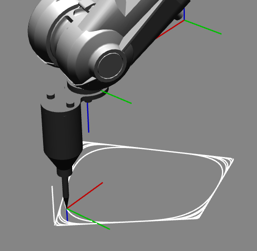
The resulting motion should look something like this:
Assignment 2 Part B
The method of working in Part A was efficient in the sense that we were able to define as much incremented motion as we desired using only four robtargets. However, copying and pasting the code and finding and replacing the zonedata can become tedious. Furthermore, the default values of zone data are limited to fine, 0, 1, 5, 10, 15, 20, 30, 40, 50, 60, 80, 100, 150, and 200. While we have the ability to define new values for speedata, this too can become tedious without recursion, which is beyond our current scope. For Part B:
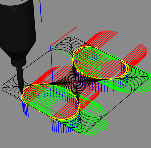
- Using Grasshopper, find the centroid of the quadrilateral and create four triangles instead of a single quad.
- Incrementally fillet the triangles using a Series Component.
- When the design is to your liking, bake the geometry into Rhino and export the selection as an ACIS (*.sar) version 3.0 file.
- Import the ACIS file into RobotStudio and using autopathing to create RobotStudio paths from Grasshopper geometry.
Assignment 2 Part C
While autopathing allows us the freedom to convert Grasshopper-generated curves into RobotStudio paths, this operation can only be done to a single curve at a time, which is very tedious. For Part C:
- Modify your Grasshopper definition to turn your entire design into one single curve.
- Because we must rationalize the curve into a one degree polyline in RobotStudio, add this step into your Grasshopper definition so that you are controlling this rationalization using a target segment length. Remember, only apply this rationalization routine to the fillet arcs as it would be quite inefficient to add segments to our straight runs.


No comments