Horizontal Public Connector
Throughout history bridges have been a focus of legends of every civilization. Esthetes, philosophers and poets have used the bridge as a transcendent form.
Author unknown
OBJECTIVE
Exploration of natural and formal ordering systems and their capacity -to inform in two and three-dimensional design (SPC A.5)
Articulation and Development of a design language based on investigations of line, plane and volume
Documentation and Analysis of site/context
Development of Architectural ideas/concepts relating to the activation of space through notions of inhabitation and circulation; horizontal vs vertical movement, enclosure, bridging, transition, and experiential events.
Development and generation of Models and Graphic representation to reflect design intentions
Understanding and exploring concepts of scale, proportion and order
DESIGN PARAMETERS
- The new link will replace the existing two-story walkway at the designated site.
- The overall dimension of the new bridge design may not exceed:
20’ width x 20’ height x 55’ length - The floors at the existing 5th and 6th floors of the buildings adjacent to the bridge will be combined to be double-height, public spaces.
- The degree of enclosure and operability of envelope will be determined by each student.
- Additional program may be proposed by each student.
SITE
The site for this project at Prospect Street, between Pearl Street and Cadman Plaza, Brooklyn. Reflecting the dramatic changes in the DUMBO neighborhood, the existing buildings in this area have changed owners and are presently being redesigned to accommodate DUMBO Tech Triangle offices. Formerly owned by the Watchtower society, the buildings are linked by several existing walkways. In the near future, the Brooklyn Tech Triangle will take ownership of the buildings and open them to local artists and their studios as well as their offices. Your task is to design a new link to replace the existing two-level connection, enhancing the vibrant connectivity among the new and diverse tenants and programs, between the buildings and this unique urban context, creating a gateway into DUMBO.
PROCESS + SCHEDULE
PART 1: Site Observation, Documentation + Interpretation
Virtually visit the site via Google Earth, and Google maps. You may also visit physically if safe. Through photoshop and sketching, document spatial conditions, materials, site conditions and general scale of the area.
Each student will construct a façade model with foam core, incorporating the two facades being bridged, along with the ground plane.
DISCUSSION
What is a “site?” What are basic site characteristics / forces that can shape your design idea?
Site Observations – what can you learn about the site?
EXERCISE
Visit the site virtually (and physically, only if safe) to observe and document a variety of conditions. How might the site conditions vary among visits?
Document the site – capture your observations through sketches, photographs, sound recordings etc. Make sure to take several photos, comprehensively documenting the entire site, including any site features of particular interest which could become your “springing off point” for conceptual thinking…
Interpret the site – choose a series of photographs that you will work with to develop a conceptual idea
DELIVERABLES DUE 02/03
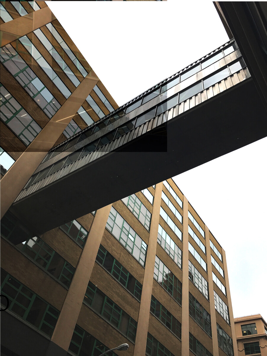
A) Collages (Photoshop)
Three (3) different collages, 11X17, black&white, comprised of ~5 photos each, posted on MIRO:
- From your initial documentation of the site, select five photographs (from Google Earth, or similar) that best convey strong spatial relationship of elements based on the list above. You may also use the following JPGS’s:
- Each photograph should fit within a 5” x 7” boundary in color, clearly labeled with the associated preposition. The orientation of the sheets will be determined by each student but should be consistent.
- Arrange the selected images in a sequence, creating a collage – 11×17″- that establishes connections between each image (the images may be manipulated digitally or by hand to explore scale, transparency, etc.).
- The photos may overlap at the edges or establish other articulated relationship between the images. Experiment with different transparencies of paper.
- Repeat this process for two additional collages based on different sets of five spatial conditions to produce a total of three collages. You may re-use images used in other collages.
B) Diagrams (Photoshop, Illustrator)
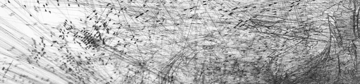
Select one of the three collages that conveys the strongest composition and spatial potential. Using one selected collage as a base drawing, overlay and extract a line composition, black&white, from your collage underlay:
- Outlines: Trace shapes and boundaries. Use line weight (min. 3 thicknesses)
- Geometric Abstraction: Look at abstract rhythms of lines or geometries rather than the actual known “objects.” Use line weight.
- Solid/void (Nolli) diagram: Create a separate figure-ground drawing from your overlay drawing, establishing solid/void relationships (no lines).
Make sure to save all work as high quality *.JPG files, and post on MIRO.
Keep in mind that you are Not literally “designing” your Horizontal Connector through these collages, but that the process will reveal vocabulary spatial conditions that are to be interpreted and developed into your final design.

