Hello, this is my academic portfolio. I hope you will like it.
Project 1
Project1 TCET 2220 Transmiss Syst-1
NEW YORK CITY COLLEGE OF TECHNOLOGY
TCET TELECOMMUNICATION ENGINEER DEPARTMENT
TCET 2220: TRANSMISSION SYSTEM
PROFESSOR: VIVIANA VLADUTESCU
SMITH CHART
FINAL PROJECT BY Romuald Ilboudo
Project 1
Guidelines: Please type all the solutions! For the Smith Chart use Tools/ Typewriter to inset symbols or text. Email and UPLOAD your project 1 on your ePortfolio. In addition to this poject you also need to upload Project 2 and the reflections on the seminars/workshops/field trips, and email them to me.
- A 0.334λ long Z0=50 Ω T-line is terminated in a load ZL=100-j100 Ω. Calculate and use the Smith Chart to find:
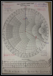
a)ΓL;
zL = = = 2 – j2
ΓL = 0.62; we determined it from the graph by projecting along the RADIALLY SCALED PARAMETERS.
b)VSWR;
From the same projection also we did find that the VSWR is equal to 4.25 (VSWR = 4.25).
c)Zin seen by the source.
Zin = (0.55 + j0.89) = 27.5 + j44.5
- Suppose a Z0=50 Ω T-line is is terminated in a 100 Ω load. Determine the aquired impedance of a quarter-wave matching section of T-line.
Find Z1: Z1 = = = 70.71Ω
- Suppose a 50 Ω coaxial cable made with a Teflon dielectric, that must operate at 800MHz T-line is terminated in a ZL=10-j15 Ω. Use the Smith Chart to
a) Create a matching network by adding a reactive element at a suitable location along the T-line:
ZL = 10 – j15Ω
F = 800MHz
Z0 = R0 = 50Ω
zL = = = 0.2 – j0.3Ω
b) determine the length of the coaxial line between the load and the capacitor:
ynew = 1 – j1.95
d= 0.314λ – 0.201λ= 0.113λ
l= 0.5λ – 0.314λ = 0.186λ + 0.186λ = 0.372λ
c) determine the value of the series capacitor added to provide an impedance match:
1.95j = Xc
1.95j =
1.95j =
1.95 =
C =
C = 1.02pf
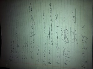
- You would like to match a 170Ω load to a 50 Ω T-Line.
(a) Determine the characteristic impedance required for a quarter-wave transformer.
R10 = = 92.19Ω
Zs = 92.19 []
Zs = 42.66Ω
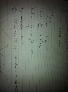
- Consider a 6 cm long 75 Ω transmission line terminated in a 125 Ω load and having a matched source impedance (Zs = 25 Ω). Propagation velocity on the T-Line is 0.1c. The source is a 0.4 ns square pulse of amplitude 4V.
V+1 = = = 3.33V
VL = = = 5.39V
V–1= (V+1) ( = (3.33) (0.62) = 2.06V
VOLTAGE STEADY STATE IS:
V+1 + V–1 = 3.33V + 2.06V = 5.39V
Project 2
TCET 2220 Project 2 Alossessment
Romuald Ilboudo
Transmission System
05/13/2013
Load Pull
In transmission system, load pull is the process of constantly varying the impedance of a device under test (DUT). Load pull doesn’t require the variation impedance at the load port since the impedance can vary at any port of the DUT. Load pull is a very important technique and it is the most widely used technique for estimating device performance in a non-linear domain.
Most of the calculation needed for load pull can be done using the Smith Chart. As I said, load pull requires the variation impedance of the load port. This means that load pull can be use to estimate (calculate) the impedance of a device. Also, load pull is used for coefficient reflection calculations. Load pulls are effective tools to precisely and rapidly determine the optimize matching parameters for a transistor device.
Fig. 1 A load pull system shows with a Smith chart.
Credit of this picture to Mohammad S. Hashmi and Fadhel M. Ghannouchi
According to Mohammad S. Hashmi and Fadhel M. Ghannouchi, a load pull system is composed of an active or passive impedance-tuner, the controlling mechanism to precisely set the tuner impedance to achieve desire impedance, and equipment to measure the traveling wave at the input and output port of the DUT.
They are two types of system used by load pull applications. Theses are the active load pull system and the passive load pull system. These two applications have different properties and using them depends of the type of issue we need to solve, more precisely, it depends of the type of impedance tuner used.
An active load pull system is usually used for applications requiring high reflection coefficient value. While the passive load pull is used for application that required high-speed measurements. Note that there are frequency limit for any of the type of load pull used.
The figure below shows an active load pull system. The figure shows two closed loop in the load pull system: an active open loop (a), and an active closed loop (b). In a closed loop structure of the load pull, they are oscillations. The oscillations are due to the reflective traveling input wave. The oscillations can be overcome with an amplifier with high gain and high linearity in the feedback loop.
Fig. 2 Active load pull (a) active open loop load pull, (b) active closed loop load pull. Credit of this picture to Mohammad S. Hashmi and Fadhel M. Ghannouchi
Active and passive load pull can be combined to create what is called a hybrid load pull.
When applying load pull with a Smith chart, sometimes, they are the need to reduce the Smith chart coverage to provide the ideal match between the wave transformer and the load pull tuner. This is done by adding a λ/4 in the load pull system.
In load pull, we have to differentiate between the λ/4 transformer and the Klopfenstein transformer. The main difference between the Klopfenstein and the λ/4 is that the Klopfenstein covers much bigger distances than the λ/4. But both the Klopfenstein and the λ/4 are used to reduce the size of the Smith chart.
Nowadays, they are two developments is load pull configuration. These two developments are the loop passive load pull and the envelope load pull. The loop passive load pull is the most worldwide technique used in load pull.
View all that have been said above, load pulls are very important and indispensable in transmission line. Load pull was created more than 40 years ago, but still they are commonly used nowadays. As a student in telecommunication, transmission systems are a very important topic. And in transmission system, load pull is important. The paper also allowed us to see a practical example of the Smith chart in real life.
Sources:
M. S. Hashmi, F. M. Ghannouchi, P. J. Tasker, and K. Rawat, “Highly reflective load pull,” IEEE Microwave Mag., vol. 12, no. 4, pp. 96–107, June 2011.
F. M. Ghannouchi and M. S. Hashmi, Load-Pull Techniques with Applications to Power Amplifier Design, Springer Series in Advanced Microelectronics, New York, NY: Springer, 2012.
F. M. Ghannouchi, M. S. Hashmi, S. Bensmida, and M. Helaoui, “Loop enhanced passive source- and load-pull technique for high reflection factor synthesis,” IEEE Trans. Microwave Theory and Techniques, vol. 58, no. 11, pp. 2952–2959, Nov. 2010.
F. Secchi, R. Paglione, B. Perlman, and J. Brown, “A computer controlled microwave tuner for automated load pull,” RCA Review, vol. 44, no. 4, pp. 566–583, Dec. 1983.
Introduction to Load-Pull Systems
And their Applications
Part 43 in a series of tutorials on instrumentation and measurement
Mohammad S. Hashmi and Fadhel M. Ghannouchi
BNL trips
BNL Internship Summer 2013Introd to load pull syst and applic
Brookhaven National Laboratory
The Brookhaven National Laboratory
The Brookhaven National Laboratory (BNL) is a science laboratory located in Long Island. The BNL was created in Camp Upton, a former U.S. army base. BNL is owned by the United States Department of Energy. The BNF offers many services which include the nuclear and high-energy physics, physics and chemistry of materials, environmental and energy research, Nonproliferon, neuroscience and medical imaging, structural biology. Also, some of the scientists working at the BNF won the science Nobel price. The BNF is sometimes opens to public, and always open to academics and students who come from to visit, or do researches in the BNL laboratories.
On Friday, May 24 2013, I had the chance to participate to a field trip organized by my college (the New York City College of Technology) to visit some departments of the BNL. The first thing that brought my attention was the nice and welcoming place where the BNL laboratory is implanted. Also, staffs and professors working there were nice and encouraged us to ask questions. We visited three departments at the BNL that are: the National Synchrotron Light Source, the Center of Functional Nanomaterial, and the Relativistic Heavy Ion Collider Overview.
The first department we visited was the National Synchronous Light Source. The tour was assured by Dr. Lars Ehm. Basically he told us that their main concern at this department was about working with light for researches in biology, physics, chimistry, and geophysics. Dr. Lars Ehm who is a geophysist told us that this technique was widely used to study phenomenal events such as earthquakes, tsunami, and volcano eruptions. Synchrotron light is produced by electrons when they are forced to move in a curved path at nearly the speed of light. At the NSLS, beams of light in the x-ray, ultraviolet, and infrared wavelengths are produced by two synchrotrons for use in experiments. This department welcomes 2,400 researchers from more than 400 universities every year.
Then we visited the Center of Functional Nanomaterial. Dr. Aason Stein welcomes us in this department. To repeat what Dr. Stein said, the goal of their department was to apply physical, mathematical, and chemistry laws in an object of 1 nanometer long. He also explained us that to achieve their goals, scientists in this department use two different methods: the up-to-down method, which consists of starting from a big objet and going smaller, and the down-to-up method, which starts from a small size and grows big. The Center of Functional Nanomaterial was far the one I liked. I was able to see rooms where scientist was actually working. This was a great experience foe all of us.
The last department we visited was the Relativistic Heavy Ion Collider Overview. Dr. Vincent Schoefer, who welcomes us at this department, explained that their goal in this department is to study how the universe works. How our World was created. To do so, they try to recreate everything that happened in the universe in their laboratories. As he told us, they were able to go up to 10s before the Big Bang happened. They still do researches to go even farer.
As I said, visiting the BNL was a good experience. I asked how I could get an internship at the BNL and they tell me that they are very selective. They only accept students with FPA of 3.5 and up. Right now my GPA is 2.9, but now I know that I have to work better since I really want to apply for an internship at the BNL
Homeworks

