Find below an example of how to determine the position for your pneumatic cylinders in your projects. This is an example I have adapted from the book Mechanical Design for the Stage by Alan Hendrickson. If you are interested in machine design, I highly recommend that book.
- First, draw (or download) your cylinder in your CAD program of choice. I downloaded a sample cylinder from McMaster-Carr (part number 6498K658). I had to adjust the model slightly to show the full size of the part. The retracted position is shown in white, and the extended position is shown in magenta. It will help to make this part into a block for later.

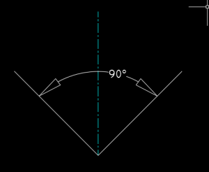
- Next, draw a schematic for the motion you are trying to accomplish. In my example, I will open a door 90 degrees, just like the class project. Draw the centerline (blue) and angle of motion (white) as shown below.
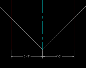
- Since the cylinder I chose has a 6″ stroke length, I then offset the center line 3″ to each side. You will need to adjust this distance based on the stroke length of your cylinder.
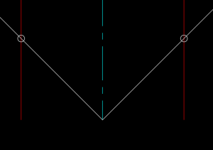
- Next I drew a circle at the point where my angle (the white lines) intersect the offsets (the red lines). This will help me accurately position the cylinder in relation to these points.
- Now I can add the cylinder block from earlier into the drawing, and turn the whole thing into a new block. The end of the extended rod should touch one circle, and the close position should touch the other circle. The base point of the new block should be the vertex of the angle (where the white lines meet).
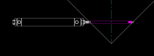
- You can use this block to position your cylinder in your model. You can place the base point of the block at the center of the hinge pin in your drawing, then rotate the block until it lines up with the position of the door (or whatever you are moving). Be sure to use OSNAPs for this, so that your model is accurate.
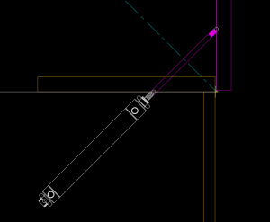
Note that this is only a rough placement to see if your cylinder will fit. To get a more exact placement, you would need to draw all of the connection details for each end of the cylinder.


