Python Tutorials

Before Class on Tuesday May 20th. Please watch and review all 10 of these Intro to Python Scripting Videos. Most are under 20 minutes. Don’t just copy and paste the code, instead try and follow along with the video and type the code as you go. We will start Tuesday off with a short quiz and then dive deeper into python.


Assignment 07 CNC Milling Study + Presentation Boards for Exhibition

1.   Milling Techniques Study

Besides the milling due Friday, May 16th, you should also complete this short exercise on milling techniques that will lead you to be a knowledgeable CNC-based designer. Click here.

2. Presentation Boards (Responsive Components and the Height Mapping projects)

Our class will also be participating in the Intersections Exhibition so having professional looking boards will be very important because there will be many visitors from out of the school (perhaps even including a future employer….). You should begin filling in the attached presentation layout:

  • As a class we will be using a special font you will find in the Zip folder in the Assignment Resources folder. Click here.
  • This will be due before the beginning of class Tuesday.

An example of the Milling techniques study and the presentation boards is referenced here for you to study as you begin work. (http://www.slideshare.net/BrianRingley/arch3590-sp13-finalboardssample?ref=https://openlab.citytech.cuny.edu/compfab/course-files/)

Mill time calculations: Right click on a milling path in the Machine Operations Browser, next select Information.

–Profile path (see video 4: http://vimeo.com/album/2632220) if you would like to trim the edge of your project

–Saving images of draft angle and min. radius analyses  (see video 1: http://vimeo.com/album/2632220. Alternatively, use the Snipping tool in the Program > Accessories folder .

The Assignment Resources folder with all of the above mentioned resources is at this link: https://www.dropbox.com/sh/92y3ty93ciagk70/AACl2x4oY8Tal8iPG_H39gFFa



Assignment 06 Image Height Mapping_Milling

Grading breakdown_Sp14

Assignment 06  Height Map Milling

Part I of this assignment is due before class on Tuesday, May 13th, 2014.

Part II is due before class on Friday, May 16th, 2014.

Part I Rough and Finish Path Creation

Finish creating 1) a Roughing Path, and 2) a Parallel Finishing Path in RhinoCAM for your surface pattern:

  • Use the template file (found here) and replace the existing part with your own surface.
  • Use the RhinoCAM settings spreadsheet for this assignment (located here) and the Rhino CAM Primer located here).
  • Generation and Simulation of the tool paths. Generate each path as you finish it. Next, run the simulation with the tool and tool holder highlighted (and tool path off). These settings are selected with the bottom left corner buttons when you are in Simulation mode. Watch for any collisions (these will be highlighted in red on your model).

***Note: Hide your foam layer and turn the stock preview off to allow the path to generate.

  • Save your path as you exit the Machining Operations Browser panel. The code for milling will be contained in your Rhino file, as RhinoCAM works fully inside Rhino software.
    • Indicate the screw locations on a wireframe planview of the palette (ie. B2, B6, etc.) where you would like to have the foam/mdf piece attached to the palette). Print this to pdf.                                                                [More…]

Assignment 05 DIVA Daylighting Simulations For class May 2, 2014

Take the Cleaned Up Model file [https://www.dropbox.com/sh/uvp89ere37afxzm/yuigbDThO4]      with your responsive component design placed on the SOUTH facade. You will be running a number of analyses in DIVA as described below and documenting them.

As designers, the main concerns in working with the South Facade are to 1)help control glare and heat, and 2) reflect light more deeply into the space.

I. Confirm that when you are in “Top” view, North is up (positive y-axis); rotate your model if you need to.

II. Set the OBJ export options (you may need to do this every time you work with a new computer in the lab, especially if the minimum and maximum lighting levels are the same). Just to be safe, follow these steps:

  • Select all your geometry, and type “export”, and hit enter.
  • Select file type “OBJ”, and click “Options”
  • Make sure your settings are identical to the settings in this screen grab.
  • Click OK, and export the file to your Desktop.
  • Continue to work on your original Rhino file, and DIVA will be set up to perform properly.

III. Make sure your component surface and structure are scaled correctly for the rhino file [Refer to the East West video]

IV. Keep the location and material settings used in the DIVA workshop during the last class, but change the node grid size to 1.5 feet.

V. Do an initial Illuminance run on March 22 12 pm. Try offsetting your surface 6′, 3′ and 6″ from the south facade. Choose the offset distance that results in the lowest light levels to work with.

VI. Run the following Illuminance analyses in plan view (be sure the roof layer is turned on for this step):

Spring/Fall Equinox (2014)

  • March 22, at 9 am/12 pm/3 pm.
  • Sept. 22, at 9 am/12 pm/3 pm.
Winter/Summer Solistice (2014)
  • Dec 21, at 9 am/12 pm/3 pm.
  • June 21, at 9 am/12 pm/3 pm.

Save each of your  simulations with a  color gradient from blue to red (for this you will turn the roof layer off and choose shaded rather than wireframe settings)  to Dropbox and to your flash drive

Organize your simulation outputs in a grid in InDesign [https://www.dropbox.com/s/rrksl5wbrvpbff7/Decathlon%20Simulations.indd] to allow for easy visual comparison, providing titles that indicate the setting parameters used.

EXTRA CREDIT: Adjust your component design to improve the performance on the South facade (see the problem objectives above) to reduce glare on the node surface or bring light further into the space. Rerun the simulations and organize the documentation in the InDesign grid.


solar decathlon floor plan

https://www.dropbox.com/s/7sigzyhj7vn7ws1/Arch-3630-Assignment-13-Olivier-de-Marc%281%29.3dm

Assignment 04 Responsive Component Fabrication (See full Assignment in Assignment Menu)

Description

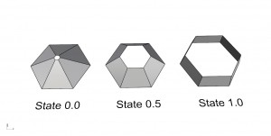
Fabricate your responsive component.  You should now have a responsive component in Grasshopper that responds to an input parameter control with a range of 0.0 to 1.0.  Using the laser cutter as your fabrication technique create 3 versions of your component that represent 3 unique states of your component.  You can choose any 3 values from 0.0 to 1.0 or you could use the end and middle conditions, for example 0.0, 0.5, 1.0.


Requirements

Fabricate the 3 states of your component.  You will have 1 week to complete this assignment.  It will be due on March 18th.

  1. The 3 laser cut states of your component need to be fabricated at an appropriate scale to convey a moderate level of detail to illustrate the assembly.  Because of wide variation in the scale of everyone’s components, it is difficult to provide a scale that would apply to everyone’s unique components.  That being said, your scaled down components should roughly fit in an 8″ to 10″ cube.  To be clear, each component would fit into it’s own 8″ to 10″ cube and you will provide 3 of these at 3 different states of responsiveness.  These are to be fabricated using laser cut bristol board.
  2. You will also need to provide an image/rendering/screenshot of your component applied to a surface to illustrate the overall scale of your component.


Scoring

  • Design : 20%
  • Demonstrates Proficiency with Tool and Lasercutter: 20%
  • Labeling /Organization of Dropbox and definition/ Correct File Naming: 5%
  • Followed Assignment Directions: 5%
  • Rendering/Image of component applied to surface: 10%
  • Laser cut Fabricated Components: 40%


Resources

Check out these resources for more info on the responsive components and the laser cutter assignment.

Spring 2014: Responsive Component 2

Spring 2014: Responsive Component

Fall 2013: Responsive Component


Assignment 3

Assignment 03 (Spring 2014)

Description

Define a Surface in a 12″ x 12″ x 12″ volume. Create a revolved surface. Use the Panel component to describe and comment/label your definition.

Requirements

Create at least 3 versions of a revolved surface geometry. Please save your grasshopper (.gh) files to your dropbox folder. Please create a separate grasshopper file for each version. Refer to the syllabus for the file naming conventions for dropbox submissions.  These are due before the next class on Tuesday 02/18/14.  Late assignments will receive a grade penalty.

Scoring

  • 3 versions : 45%
  • Fits within the bounds of the volume (12″x 12″x 2″): 20%
  • Demonstrates Proficiency with Tool : 25%
  • Labeling /Organization of Dropbox / Correct File Naming: 10%


Resources

Class Video:

Spring 2014: Revolve and Panelize

https://vimeo.com/86718485
Fall Videos:

Fall 2013: Week 5 Panelization Part 1

Fall 2013: Week 4 Revolve Surface

Assignment 02 (Spring 2014)

Assignment 02 (Spring 2014)

Description

Define a pattern in a 12″ x 12″ x 2″ volume. You may use attractor geometry or combinations of geometric transformations. Use the Panel component to describe and comment/label your definition.

Continue reading

Spring 2014 Assignment 01 Math Components

Assignment 01 (Spring 2014)

Description

Using the example files create the number patterns in Grasshopper.  Using the refer to the class video below for a review of the Math components in Grasshopper.

Continue reading