
Final Week
As a reminder – print BOTH section drawings for class Wednesday. We will go over the drawings in class – you will have an opportunity to make changes to your drawings for Friday.
Friday we will have an in-class, open-book test. Bring a pencil, paper and a scale ruler to class. You will need to submit the final version of your section drawings to OpenLab before class on Friday.
Assignment 23: Drawing the elevation for the new section
Follow the same steps for the previous two assignments to draw the building beyond our new section.
- To help us, xref the scan of the building elevation that matches our section, and scale it to match.
- Place this elevation behind your section drawing so far, and use xlines to identify key building elements (the top of the tower, for example). You may also be able to identify useful heights, such as the ceiling heights of individual floors. Draw your silhouette line (A-SECT-SILHOUETTE) from this elevation.
- Look carefully at the elevation and the plan together. A big part of Wright’s design for the house is the overlapping volumes of three different materials: stone, concrete and glass. You will need to understand how the volumes move through the different floors to be able to draw the section.
- Now use xlines to identify key parts of the elevation for each floor, and draw them on A-SECT-BEYOND. If you come to a doorway, remember that you must draw the door header, so you will have to figure out how tall the door is.
- Friday we will continue to add elevation hatches and complete our drawings.
- Bring a printout (full size) of your section to class on Wednesday, December 13.
Assignment 22: Surfaces and Materials in Elevation
- Go to your X-SECTION.DWG file, and select the layer A-SECT-ELEV-HATCH that we made on Wednesday.
- Find an area that shows up in stone in the section we have been tracing.
- Use bhatch to create a hatch in that area – if you haven’t been careful with your drafting, you may need to trace the area (on DEFPOINTS) with a pline to create a closed area to hatch.
- Make a custom hatch, with horizontal lines about 4″ apart.
- Apply this hatch to any visible areas of stone in the traced section.
- Update your PDF drawing and post it to OpenLab by Wednesday, December 6.
Assignment 21: The Elevation beyond
We will continue looking at drawing in section, specifically drawing the elevation view beyond the section cut.
- In your X-SECTION.DWG file, go back to the section you were tracing.
- Make a layer called A-SECT-BEYOND, color Red.
- Make a layer called A-SECT-SILHOUETTE, color Yellow.
- Make a layer called A-SECT-ELEV-HATCH, color Grey (color 8).
- Starting with primary elements beyond the section cut, draw temporary xlines to identify how those elements show up in each of the plans. Measure the height of important elements above 0′-0″, and make a note of that.
- Using A-SECT-BEYOND, trace the lines in the elevation onto your drawing. Keep things simple – use plines wherever possible, make sure that lines meet each other, and don’t draw surface textures – only features which are visible in plan.
- Now using A-SECT-SILHOUETTE, trace the outline (between building and not-building) of the house and landscape.
- Update the PDF of this section that you made in Assignment 18, and post it to Openlab by Wednesday, December 6.
Assignment 20: Drawing Stairs
Our new section cuts through one stairway (down to the lowest terrace), so we will need to draw those stairs in section.
- In your Basement plan, carefully count the number of risers (vertical faces) in the stair. Each line on the plan should correspond to a riser.
- Look at your X-SECTION.DWG file. Convert the distance between the Ground Floor and the Basement Floor into inches, and divide that distance by your number of risers. This will give you the height of each riser. We will call this dimension ‘y’.
- Examine the stair construction in this photo: https://www.dropbox.com/s/5pir4o5hkfnc0fy/134151pv.jpg?dl=0. You will see that the stair is composed of individual planks, suspended from steel bars, which also serve as the railings.
- Now draw vertical xlines from each stair line on the plan, to locate the front edge of each tread. The distance between these lines we will call ‘x’.
- Draw horizontal xlines starting at the Ground Floor level, and use the array command to copy them, y inches apart, down to the Basement floor level.
- Let’s make the treads a nominal 1-1/2″ thick – draw a rectangle on the ‘A-SECT-CUT’ layer that measures ‘x’ by ‘y‘.
- Stretch the rectangle by 1″ to account for the overlap between treads.
- Copy your tread into the proper locations (remember there is probably no top tread). Delete your xlines.
- Now draw a line in the ‘DEFPOINTS’ layer connecting the top-front point of the bottom tread and the top tread. Copy this line 7′-0″ vertically – the space between these lines is the space that a human walking down the stairs would occupy. Does this area intersect any solid object that you have cut through?
- Finish adding grid letters, elevation labels, anything else to your new section.
- Post a PDF of your new section to Openlab by Wednesday, November 29.
- Read Allen and Iano Designing Exterior Wall Systems pp 783-807, Ching Chapter 6 pp 6.02-6.30 and Ching Chapter 5 pp 5.02-5.03, and post your notes to Openlab.
- Have a good Thanksgiving!
Assignment 19: Cutting a New Section
In class we will begin making a new section drawing based on the plans that we have so far.
- In X-SECTION.DWG, start by loading only the xref for X-PLAN_1.DWG.
- Begin by choosing a location for a new section cut perpendicular to the section we have been examining. Draw an xline at this location.
- Look carefully at every line that your section line touches the ground floor plan. What changes at that line?
- Copy your elevation levels from the other section, and rotate them so that they are oriented properly for your new section. Make sure to leave enough space for the drawing you will make.
- Extend your grid lines from the plan grid exactly as you have done in the previous section. Add bubbles at the top and bottom.
- Now make temporary xlines at places where your section line crosses primary walls and parapets. On the ‘A-SECT-CUT’ layer, draw lines between the 2nd floor elevation and the first floor elevation at those locations on your section.
- You will need to work out heights for parapets and window sills and headers. Make a horizontal xline at these levels above the ground floor elevation, and use the trim command to cut the parapets to the correct height, and make the window openings. Draw short line segments to close off the walls. Draw horizontal line segments to make a floor between the walls.
- Figure out the ceiling heights in the various spaces (the height on the terrace may be different than inside). Draw temporary xline at those elevations.
- Now load the xref for X-PLAN_2.DWG.
- Draw xlines for the extent of the terrace or floor on the second floor, and use those to complete the ceiling of the ground floor.
- Before you continue with the other floors, select all the lines you have drawn and join them. Use the fillet command to radius corners of balconies and sills.
- Repeat for Basement, 2nd and 3rd floors. Fill in as much as you can of the primary section cut line – you may have to look at the other sections or at the elevations if you can’t figure out the height of elements.
- Copy your section page layout, and print a PDF of your new section drawing – post to OpenLab.
Assignment 18: Sectional Structural Analysis
Fallingwater was a daring structural design at the time that it was built. The house appears to levitate over the creek below. Even though we don’t have a clear structural grid, we can develop a reference grid by carefully studying the plans:
- First, make a file for the basement floor, called X-BASEMENT.DWG.
- First, xref the X-GRID.DWG into the file (as an overlay).
- Insert the image of the plan and scale as before.
- Move the image to align the corner of the terrace above with the grid file.
- Save this file, and go to X-GRID.DWG.
- Xref your X-BASEMENT.DWG file into X-GRID.DWG.
- Create grid lines on the X-GRID layer as we have done before (Circles 1” diameter, text 1/4” guidelines, letters left to right, numbers top to bottom).
- Xref in each of the upper floors, and add further grid lines as needed.
- Transfer the relevant structural grid to your section.
- Make a layer called X-GRID-SECT in X-SECT.DWG.
- Use xline to locate the grid lines that are perpendicular to your section cut.
- Draw vertical grid lines on your section, with circles above and below your section, properly labelled.
- If you have not, draw level lines on your section for the floor levels. Add measurements , treating the ground floor as 0′-0″.
- Start a new page layout in your X-SECTION.DWG file, 24″x36″ (landscape), 1/4″ = 1′ scale, with your section drawing: include the grid lines, cut lines, and glazing.
- Submit a PDF of this drawing on Openlab by Wednesday.
Assignment 17: Sectional Envelope Analysis
We will continue to explore Fallingwater in section.
- In the file X-SECT, make a new layer A-SECT-GLAZING, color Yellow, and use it to draw the window frames and glazing for your section. Keep the window frame simple, but remember to make the glass thick – use two lines, or better yet a complete rectangle.
- Now make two new layers A-ANALYSIS-INTERIOR and A-ANALYSIS-EXTERIOR, and trace the inside space at each floor and the exterior envelope at the section cut. If you have been careful at your drafting (and used mostly polylines), you may be able to do this very quickly using the bhatch command – we will go over this is class.
- Make a sheet layout for your building section in 1/4″ = 1′ scale, with a titleblock, and plot a PDF. Submit this PDF by next Wednesday, November 15.
Assignment 16: Facade and Envelope (5 sketches)
For Friday, we will meet at the Barclay Center at the front door (under the big hole with the video screens on all sides). Bring your sketchbooks.
Assignment 15: Section Drawings and Analysis
We will begin working with a new building, Frank Lloyd Wright’s Fallingwater, in Autocad:
- Download an image of the drawings here. Place them in the folder where you will keep your drawing file.
- Make a new Autocad file, and save it as ‘X-PLAN_1.DWG’.
- Insert the image file ‘Fallingwater_Floor1.TIF’ into the Autocad file. Make sure the image is on the ‘0’ layer.
- Select a dimension on the image, and use it to scale the image to the correct size (we will do this in class).
- Make a new Autocad file, and save it as ‘X-SECTION.DWG’.
- Use xref to insert X-PLAN_1.DWG into the file.
- Again insert the image file ‘Fallingwater_Sections.TIF’ into this file, and scale it properly.
- There are two sections, so choose one of them to work with. Move and rotate the image so that it is outside your plan, and corresponds to the correct section.
- In X-PLAN_1.DWG, make a new layer: ‘A-WALL-EXTERIOR’ (Dark Blue).
- In X-PLAN_1.DWG, trace the exterior walls on your plan (use POLYLINE!)
- Save your plan, and go back to X-SECTION.DWG. Reload the xref.
- In X-SECTION.DWG, make an xline (on layer ‘DEFPOINTS’) to location that corresponds to the section you have chosen. Make more xline to mark corresponding features between the plan and section (exterior of wall, edge of balcony, etc).
- Make an xline at the level of the first floor on your section.
- In X-SECTION.DWG, make a new layer ‘A-SECT-CUT’ (also Dark Blue).
- Trace the section cut line in your image (use POLYLINE!).
- Make new files ‘X-PLAN_2.DWG’ and ‘X-PLAN_3.DWG’ and repeat the previous steps. You can use the xref menu to turn on and off floors in your section file as you work.
- Finally, draw Horizontal Level Lines for each floor level. Use drawing conventions for elevation tag and annotation (1/4” circles with cross hairs and diagonal hatch, 1/8” guidelines for level name (above) and height above datum (below) xx’-xx”). Your First Floor level will be 0’0″. The level lines themselves should be large dashes.
- Make a new layout in X-SECTION.DWG, and make three PDFs of your drawing so far, each with only one floor showing. Make sure only your section lines and level lines show up on your drawing. Post these PDFs (and a JPG copies) on OpenLab by Wednesday, Nov 8.
Assignment 14: Module 2 Final
To finish off the Autocad drawings:
- Create a new layer called A-CLG-ABOVE, color should be read, layer linetype should be HIDDEN-2.
- Draw your ceiling beams for both floors on this layer. They will show up by default on the floor plan as a thin dashed line.
- Make a copy of your floor plan (right-click on the Layout and select Move or Copy). Rename it “Reflected Ceiling Plan”.
- Click into the viewport on the RCP layout. In the Layer menu, scroll all the way right and change ‘VP Linetype’ to ‘Continuous’. Use the ‘VP Freeze’ column to turn off any layers that should not appear on the RCP (like furniture, window sills, etc).
- Now go to the floorplan, click into the viewport, and use ‘VP Freeze’ to turn OFF window and door headers – these should only show up in the RCP.
- For the final, post a link to (4) PDF drawings: floor plans and RCPs for both floors. These files are due by Wednesday, Nov 1.
Midterm Presentations (UPDATED)
You will present your research material on a single 36″ tall x 48″ wide sheet (horizontal or landscape). There is no requirement for number of words, but you will be graded on how concisely you frame your topic (not too wide) and how completely you are able to describe it in a single board. Pay attention to the resolution of your images – if the resulting resolution is less than 200 dpi, it may appear fuzzy when you print. Make sure to do a test print to make sure your board looks good!
Here are InDesign pages for your use:
TEAMS:
We will divide the class between two teams – each person will study the structural systems of a single building (assigned in class):
Team Concrete
- Eero Saarinen – TWA Terminal
- Jorn Utzon – Sydney Opera House
- Paul Rudolph – Yale Art and Architecture Building
- Louis Kahn – Kimball Art Museum
- Le Corbusier Unite D’Habitation
- Nervi – Palazzo dello Sport
- Le Corbusier – Villa Savoye
- Louis Kahn – Yale Art Gallery
- The Colosseum of Rome
- Hoover Dam
Team Steel
- Pei Cobb Freed – Jacob Javits Center
- Frank Gehry – Bilbao Museum of Art
- Mies Van der Rohe – Lever House
- Renzo Piano and Richard Rogers – Pompidou Art Museum
- Pierre Chareau – Maison de Verre
- Charles and Ray Eames – Case Study House
- Norman Foster – Hong Kong and Shanghai Bank
- Minoru Yamasaki – World Trade Center (original)
- Gustav Eiffel – Eiffel Tower
- SOM – Willis (Sears) Tower
For Friday, I want you to know in a basic sense what sort of structural system was used for your building, why that system was chosen (what is that system able to do that another system would not?) and why it might have been considered important or advanced when it was built. Bring this information to class, and you will meet with your team to decide who will present what topic related to concrete or steel structure at the midterm on Friday, October 27.
Assignment 13: Transparency and Stairs
Continue to transfer your Library drawings into Autocad.
- Windows – we will draw windows slightly differently in Autocad.
- First, make a new layer, color Yellow, named A-WIN-SILL. Draw your window sills in this color.
- Make a new layer, also Yellow, named A-WIN-HEADER. Draw the header of the window – this layer will get turned off in your regular plan.
- Make a new layer, in Red, named A-WIN-GLAZ. Draw your glass as two layers, 1″ apart.
- When you have finished the windows, turn off all of these new layers and make sure you don’t have any duplicate lines on your regular plan – if you have a heavier line under a light line, it will still show up as the heavy line!
- Doors
- Make a new layer A-DOOR, in Red. Draw a door slab that is the width of the opening and 1 3/4″ thick, and rotate it so it is perpendicular to the wall. Make another layer A-DOOR-SWING and draw an arc for the door swing. Think through how the hinge works – make sure the door is drawn so that it can open and close.
- Make a new layer A-DOOR-HEADER, in Yellow. Draw the door header – these lines will not be turned on in your regular floor plan.
- Stairs
- Draw the stair treads, ‘up’ arrow and 45deg cut line on A-STAIR. Draw the stair treads above the cut line in A-STAIR-ABOVE, which should be Red with a ‘Hidden’ line type.
- Update your PDF plans, and post to OpenLab by Wednesday, October 25.
Assignment 12: Structure and Partitions
Continue to transfer your Library drawings into Autocad.
- You will add the structure and partitions into your “GROUND FLOOR.DWG” file and “SECOND FLOOR.DWG” files.
- Make a new layer for exterior walls that is Dark Blue, named A-WALL-EXTERIOR
- Make a new layer for interior partitions that is Cyan, named A-WALL-PARTITION
- Make a new layer for structure (columns), colored Purple, that is named S-COL
- Print updated plans using CTB file to 24″x36″ PDF, and post a JPG and link to a PDF on Openlab by next Wednesday (October 25).
Link to sample graphic scale for your use
Assignment 11: Plan Grid + Schema
We will re-draw our library plans in Autocad. We will start by making a file that contains only our grid and reference lines.
- Make a new DWG file, and save it as “X-GRID.DWG”.
- Make a new layer “GRID”
- Draw Centerlines of Primary Form
- Measure Carefully Grid Lines in Both Directions
- Labels Grids Following Convention (Circles 1” diameter, text 1/4” guidelines, letters left to right, numbers top to bottom)
- Save and close this file.
- Make a second DWG file, and save it as “GROUND FLOOR.DWG”
- Use the xref command to place a reference to your X-GRID.DWG file in your new file.
- Measuring Off Gridlines, Draw Primary Geometry (Outside Face of
Walls/Structure) Stay Schematic, Not too much detail. Use the DEFPOINTS layer to draw guidelines that you don’t want to show up when you print. - Draw in model space graphic scale showing 1’, 4’, 8’, 16’, 32’ marks.
- Make a new page layout, 24″x36″ (D-sized sheet)
- Format to scale in paper space (1/8″ = 1′)
- In lower right of drawing (2” away from sheet edges)
- Use 1/4” high text for Drawing Title (i.e. Bibliotheque S.
Genevieve Plan Underlay) - Use 1/8” high text for ARCH 1230_ClayYouman_date +
Last name + first name
- Use 1/4” high text for Drawing Title (i.e. Bibliotheque S.
- Print using CTB file to 24″x36″ PDF, and post a JPG and link to a PDF on Openlab by next Wednesday (October 18).
Assignment 10: Concrete and Steel Site Visit: Javits Center/Hudson Yards (Wednesday)
We will meet in front of the Javits Center (on 11th Avenue). Bring your sketchbooks and some means for taking photographs.
You will find and sketch (5) structural situations (take pictures too):
- Find an example of a concrete floor structure meeting a concrete column
- Find an example of a steel floor structure meeting a steel column
- Find an example of a concrete footing or foundation
- Find an example of a steel truss (steel beam made from triangulated smaller members)
- Find an example of an expansion joint between two rigid elements
These sketches are due next Wednesday – scan them and post them to Openlab.
Reading assignment (notes due Wednesday):
2.1.Allen and Iano, Concrete Construction Chapter 13, pp. 515-551, Sitecast
Concrete Framing Systems, Chapter 14, pp. 553-609
2.2.Ching, Building Construction Illustrated, Chapter 4, pp. 4.02-4.13
Chapter 5, pp. 5.04-5.09, Chapter 12, pp. 12.04-12.05
Assignment 9:
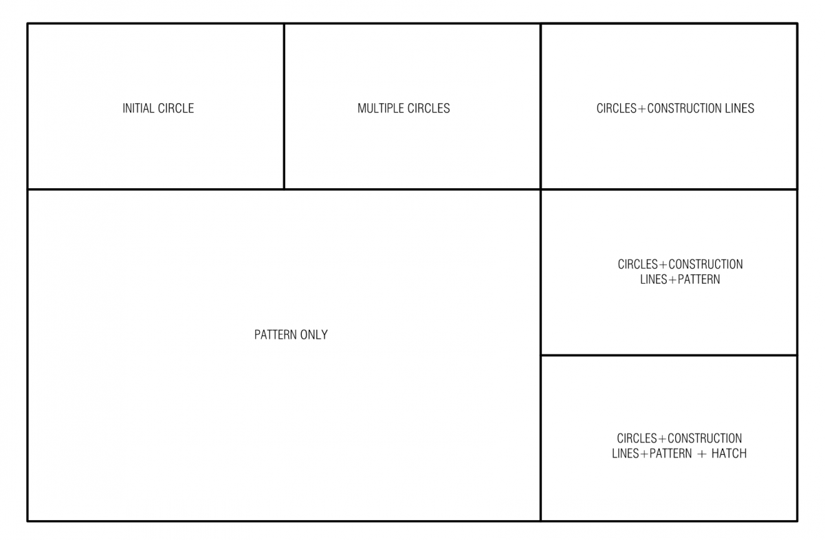
- Take the (5) geometric designs you started on Wednesday, and use Autocad’s Paper Space to break down your designs into a procedure for drawing them.
- Make a new 11×17 layout.
- You will make (6) new Viewports, laid out as below:

- Make sure that the frames of your Viewports are on the Defpoints layer. You can draw temporary Xlines to get the equal divisions correct.
- Each of your Viewports should show the exact same view.
- Change the layers that are visible in each Viewport to show the appropriate elements of your geometry.
- Think about how you might duplicate this page layout so you can re-use it for each of your five designs.
- Print your layouts as PDF files. Post on Openlab one post with JPGs of each of your four unique designs (not the one we did in class) and post a link to a single PDF with all five of your designs.
Module 2/ Assignment 8: Intro to Autocad
We will begin to learn how to leverage the drawing tools in Autocad to create 2d designs.
Here are the Autocad commands we will be using:
line
polyline
xline
circle
rectangle
ortho
copy
offset
divide
distance
hatch
object snaps
layer menu
properties menu
An Autocad template file for your use can be downloaded here.
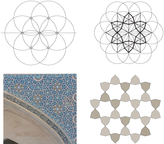
- This is an example of an Iranian geometric design derived from subdividing circles.
- Look at the initial figure. Think about what size the initial circle needs to be to fit on an 8.5″x11″ sheet of paper. Draw the outline of your sheet in your lightest lineweight. Use your object snaps and the xline command to locate the center of your sheet.
- Begin drawing your circles at the center of the sheet.
- Work with your group to figure out how to draw the second figure. Think about using your different lineweights to make it easier to tell what is going on, and to highlight the important figures.
- Make a new layer (use layer or just la to bring up the layer menu), and name it ‘Pattern_1’.
- Use the hatch command to fill only your pattern. You can now turn on and off this layer.
- You will create (4) other patterns (on new layers) using only the second figure you made. See what patterns you can find.
- You will post a PDF and a JPG image of your (4) variations. Turn on the guidelines underneath the pattern before you print to PDF, but make sure the lineweights are set up so that the pattern is the most important element.
- This assignment is due before class next Wednesday, October 11.
Module 1 Pin-up and Presentation
We will pin up on Wednesday on Exhibit Wall C, in the hall outside the classroom (use both sides of the hall).
People who did the Trinity Library will pin up as a group first, so plan to be ready to go and pinned up at the beginning of class. Think through what you will need to present your drawings effectively – they should be pinned up in an organized fashion, with sheets aligned to each other. Make sure each sheet has your name and a title on it, and the scale if that is applicable.
Reading Assignment
Ching, Building Construction Illustrated: Chapter 1, pp. 1.02-1.06, Chapter 2, pp. 2.02-2.30, Chapter 12, pp. 12.02-12.05, 12.08-12.09
Take notes as you read. Scan and submit your notes as a PDF on Openlab before next class (Wednesday, September 27)
Assignment 7 (In-class Extra Credit)
Section
In this assignment, you will begin to construct a section through the two floors of the library you have been drawing. Work in your groups – in order to get the extra credit, you must finish the assignment, scan it and post it to OpenLab by the end of class.
- Choose section location
- Select a location that you will cut through your building, parallel to the short axis.
- If possible, select a location that cuts through the middle of a window on both floors.
- Because you will have to extrapolate elevation information from photographs, choose your section cut in an area that you have as much photographic documentation as possible.
- Transfer grid lines
- Make a new layer of trace over one of your plans, leaving space for you to draw your section
- Draw the grid lines on your new sheet that are perpendicular to your section line
- Draw floor elevation lines
- Starting with the ground floor, draw light dashed lines for your two floors.
- Is the ground floor level with the ground outside? If not, what is the difference and where is this transition made?
- If your ground level is different, draw another elevation line for the ground plane.
- How do you determine the floor levels above the Ground Level? Look for clues:
- How many stair treads are used to get from one floor to another? For this exercise, let’s assume stair risers (the distance from tread to tread) is 7″
- Look at interior photos – can you use a person or a piece of furniture to estimate the difference between floors?
- Look at exterior photos – can you estimate the difference in floor-to-ceiling heights between the two floors?
- Label your elevation lines to one side, using 1/4″ text:
- “Ground Level 0’0″”
- “First Floor [elevation?]”
- “Second Floor [elevation?]”
- Starting with the ground floor, draw light dashed lines for your two floors.
- Draw your section lines
- Only draw the section cut – the line between “something” and “nothing”
- First, draw the section of the interior of each floor
- Use your plan to identify location of features below the cut line
- You will have to estimate features that don’t show up on your drawing, but try to make a reasoned estimation – you can use interior photographs to estimate the size and location of things
- Feel free to start with the general – wall thickness, floor thickness, height of window openings, and fill in more specific details later
- Your section line should be a continuous, closed line!
- Draw the section of the exterior
- Start with the ground next to your building – this should be a continuous (but not closed) line until you reach the ground on the other side of the building.
Assignment 6
Plan Overlays: Transparency + Stairs
- Transparency Overlay
- Overlay New Drawing Sheet on Structural Overlay
- Carefully Trace Structural Grid Lines + Grid identification Tags
- Draw outline of each window/door/cased opening in plan
- Title following standards for Grid/Schema
- Stairs Overlay
- Overlay New Drawing Sheet on Structural Overlay
- Carefully Trace Structural Grid Lines + Grid identification Tags
- Draw riser lines for all stairs on each level. Follow conventions for stair cutline and “up” arrow at each stair.
- Number the stair treads
- Title following standards for Grid/Schema
- Scan these drawings and post them to OpenLab before next class
Assignment 5
Plan Overlays: Structure + Partition/Millwork
For this assignment you will need 18″-wide white trace paper, a sharp pencil and an architectural scale ruler.
- Structure Overlay
- Overlay New Drawing Sheet on Plan Underlay
- Carefully Trace Structural Grid Lines + Grid identification Tags
- Draw outline of each structural pier, column, and/or wall (only structural elements)
- Title following standards for Grid/Schema
- Partition/Millwork Overlay
- Overlay New Drawing Sheet on Structural Overlay
- Carefully Trace Structural Grid Lines + Grid identification Tags
- Draw outline of each non-structural partition and millwork representing book cases.
- Title following standards for Grid/Schema
- You will make a drawing for each floor. Make sure to put your name and title on the overlay sheets!
- When you have finished, scan your overlay and underlay together for each floor – you may have to tape them together over a backing sheet. Post your scans on OpenLab.
- Reading: 5.14-5.27 in Ching’s “Building Construction Illustrated”. There will be a short in-class quiz on Wednesday relating the reading to our site visit, so as you read, think of specific examples that you say at the Empire Stores.
Assignment 4
For this assignment you will need 18″-wide white trace paper, a sharp pencil and an architectural scale ruler.
Plan Underlay
- Determine Scale and Sheet Size (1/8”=1’-0” recommended)
- Draw Centerlines of Primary Form
- Measure Carefully Grid Lines in Both Directions
- Labels Grids Following Convention (Circles 1” diameter, text 1/4” guidelines, letters left to right, numbers top to bottom)
- Measuring Off Gridlines, Draw Primary Geometry (Outside Face of Walls/Structure) Stay Schematic, Not too much detail.
- In lower right of drawing (2” away from sheet edges)
- Use 1/4” high guidelines for Drawing Title (i.e. Biliotheque S. Genevieve Plan Underlay)
- Use 1/8” high guidelines for ARCH 1230_CLAY-YOUMAN_date + Last name + first name
- Graphic scale showing 1’, 4’, 8’, 16’, 32’ marks.
- You will create (2) scaled drawings, one for each floor. Do not poche, but make sure to differentiate your lineweights. You could start by drawing everything in a thin/light line, and then go back and carefully make the medium and thick weights.
- Scan your drawings and post them to OpenLab before Friday’s class.
Assignment 3
We will meet for Friday’s class at the Empire Stores, 53-83 Water St (in DUMBO). You will need to bring your sketchbook, pencils, a ruler, and some means of taking photographs (cell phone is fine).
Update: We will meet at the corner of Water Street and Old Dock Street
You will need to identify several structural vignettes during our site walk:
- Find an example where timber structure meets load-bearing brick
- Find an example of brick being used to span a horizontal opening or space
- Find an example of new structure meeting old structure
- Find an example of a location where the direction of forces are changed (for example, horizontal to vertical)
- Find an example where expensive materials meet cheaper materials performing the same function (for example, cut stone to brick, or brick to rough stone, or brick to concrete)
For each of these vignettes, you should document with photos and sketches onsite. You will need to produce a 2d sketch and post it on OpenLab. Think carefully what the best type of drawing will show the vignette – plan, section or elevation. Shade things that are cut through, and think about lineweights.
Scale is not important, but try to make relative sizes as accurate as possible. Make sure to label your drawing and add your name.
Assignment 2
For this assignment you will need 18″-wide white trace paper, a sharp pencil and an architectural scale ruler.
Analysis 1: Library in Context
- Trace Context Plan
- Shade Library (light)
- Draw Axial Lines (Long and Short Axis) – use light dash-dot lines for axes.
- Identity Entrance to Library
Analysis 2: Figure Ground
- Trace Context Plan
- Shade Built Space
Analysis 3: Library Structure
- Trace Floor Plans
- Shade Structural Elements that are CUT in plans
- Working from photographs, add principal structural members above the plan – used dashed lines.
Analysis 4: Library Circulation
- Trace Floor Plans
- Highlight Outline of Entrance, Lobby, Stair, Entrance to Main
Reading Room - Show typical path of public circulation from the entrance to the Main Reading Room.
Analysis 5: Library Function
- Trace Floor Plans
- Hatch Book Cases
Make sure to give your drawings a title in the bottom left of the page. Scan your (5) finished drawings and post them to OpenLab before next class.
Assignment 1
For this assignment you will need 18″-wide white trace paper, a sharp pencil and an architectural scale ruler.
- Choose your building (link to folder with assignment files): either Christopher Wren’s Trinity College Library, or Henri Labrouste’s Biblioteque Saint-Genevieve.
- Find out as much as you can about your building.
- When was it built?
- Who was the architect? What other buildings are they known for?
- What sort of structure was used in the building?
- Draw two plans of your building, using 18″ x 24″ tracing paper (in ‘landscape’ or horizontal orientation):
- A context plan with
- Outlines of buildings (heavy lines)
- Outlines of walkways and roadways (light lines)
- Make sure you know which building is your library!
- Your context plan may be traced from an enlarged printout of the Google Maps image for your site, but your building must be oriented the same way as the second drawing.
- Ground and second-floor plans of your library
- All ‘cut’ objects should use a heavy line
- All objects below should use a light line
- Use a dashed line to show critical grid lines and objects above the cut plane.
- Do not poche (color in) any shapes on your drawing – only use lines.
- You can trace the digital floorplans, but your two floors should be the same size and orientation, so you can lay them on top of each other.
- A context plan with
- Find out as much as you can about your building.
- Post scans of your three plans (as JPEG files) and a short paragraph about your library on OpenLab before the start of the next class. Also bring any printouts or material you have been using in drawing your plans.

