Table of Contents
Heating, Ventilation and Air Conditioning system
In this chapter I will explain all the terms in HVAC in detail. I will also explain how those can be accomplished theoretically. I will also mention about commercial HVAC systems.
Read the Lecture on Cooling Load Calculations and Principles to understand the principles behind cooling and heating load with examples.
Also learn about HVAC component in the attached Lectures HVAC- Component Introduction
Heating Load Calculation
Cooling Load Calculation
Cooling Load Temperature Difference (CLTD) is an equivalent design temperature difference between indoor and outdoor condition at any instance.
Definition
Terminologies
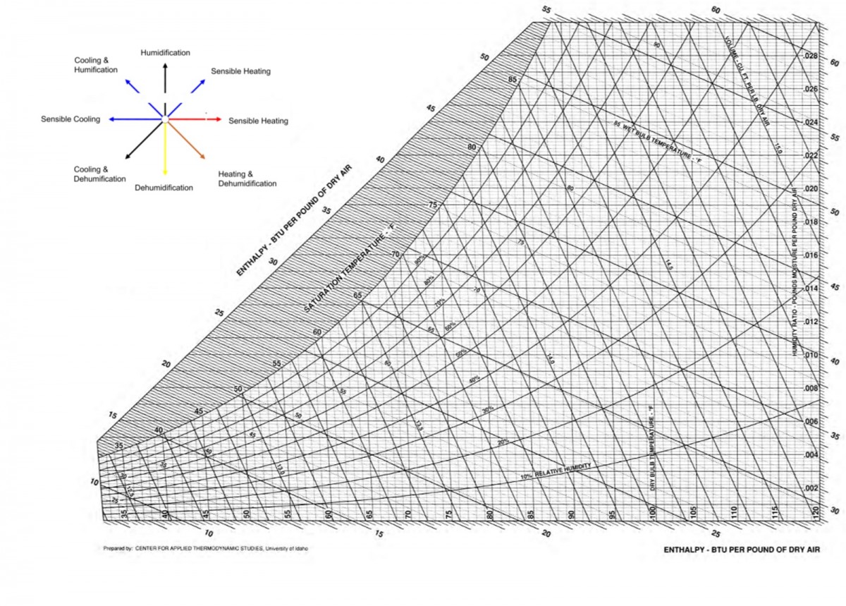
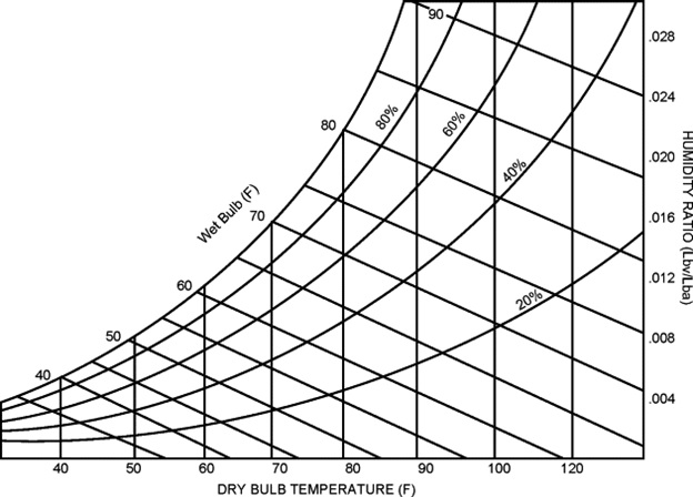
Psychometric Chart
Psychometric chart is the backbone of the detailed thermodynamic analysis of a HVAC system. It entails relationship between a number of thermodynamic properties of a state, for example, Dry and Wet bulb temperature, Latent heat, Relative Humidity and Humidity Ratio.
Relative Humidity
Humidity Ratio
[latex] x=\frac{{m_{w}}}{m_{a}}[/latex]
Where,
x=Humidity Ratio
[latex]m_{w}[/latex]=Mass of water vapor (kg, lb)
[latex]m_{a}[/latex]=mass of dry air (kg, lb)
Latent Heat
Sensible Heat
HVAC Zone
A zone is a physical enclosure or space that is to be treated by an HVAC system for the purpose of heating, Ventilation and Air-Conditioning.
Ventilation
Ventilation is a process of providing fresh air to a containment or a zone.
Natural Ventilation
Mechanical Ventilation
Mechanical Ventilation is the method of supplying fresh air or removing stale air from any given zone with the application of Mechanical devices including Fan, Blower and compressor.
Mechanical Ventilation codes can be found in the appendix .
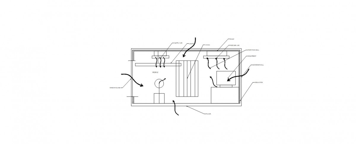
Cooling and Heating Loads in a Building HVAC system
A Building Heating and cooling loads include a number of components including
- Human
- Equipment
- Lighting
- Partition Wall
- Window Glass
These components are shown in the schematic Figure below-