We started class with a discussion of “IoT‘ which stands for “Internet of Things“—a term used to describe the growing interconnected network of smart devices. Here’s a one-minute video from November 2018 that named IoT and AI as “The Third and Fourth Industrial Revolution”—
Pundits picked up these terms when trying to explain IoT, for example in this 3-minute CBS News clip, “How the Internet of Things is changing homes and global industries”—
As you think about the examples mentioned, imagine how they work and what kinds of sensors are used to measure data from the real world—
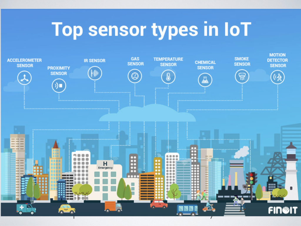
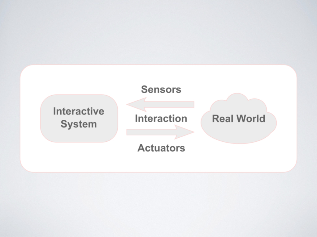
So elements in the real world are measured by sensors that go into an interactive system as INPUTS and are fed back to the real world via actuators as OUTPUTS—
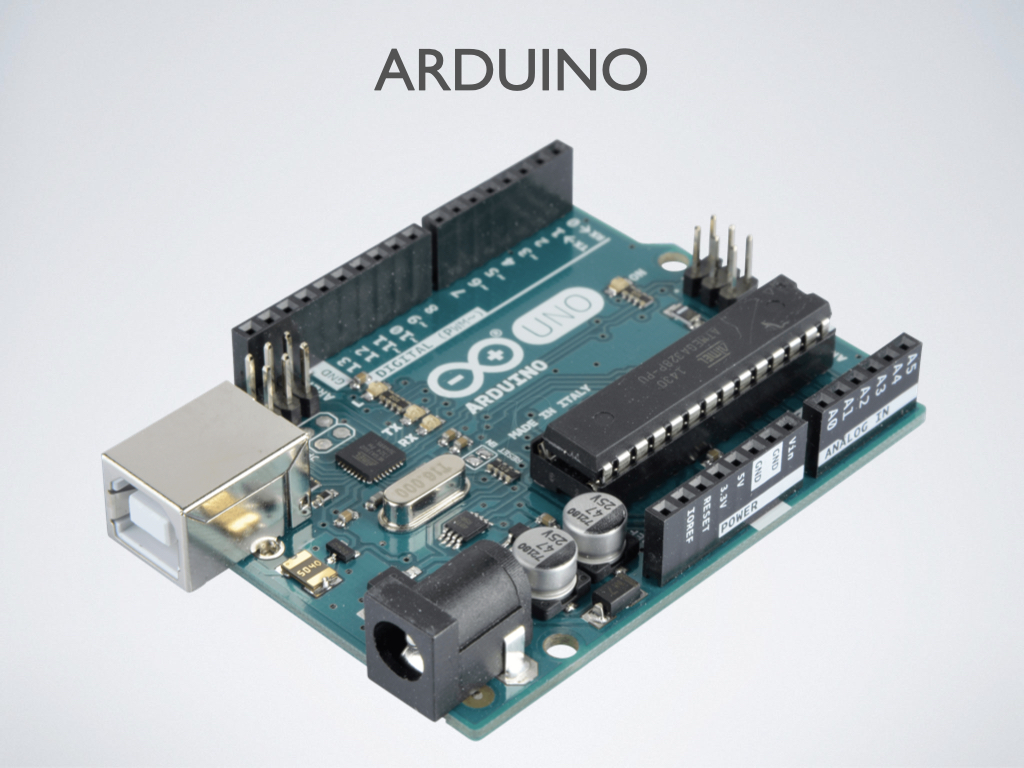
An Arduino is a microcontroller that we can use for the rapid prototyping of all kinds of projects, from fun art ideas to IoT products—
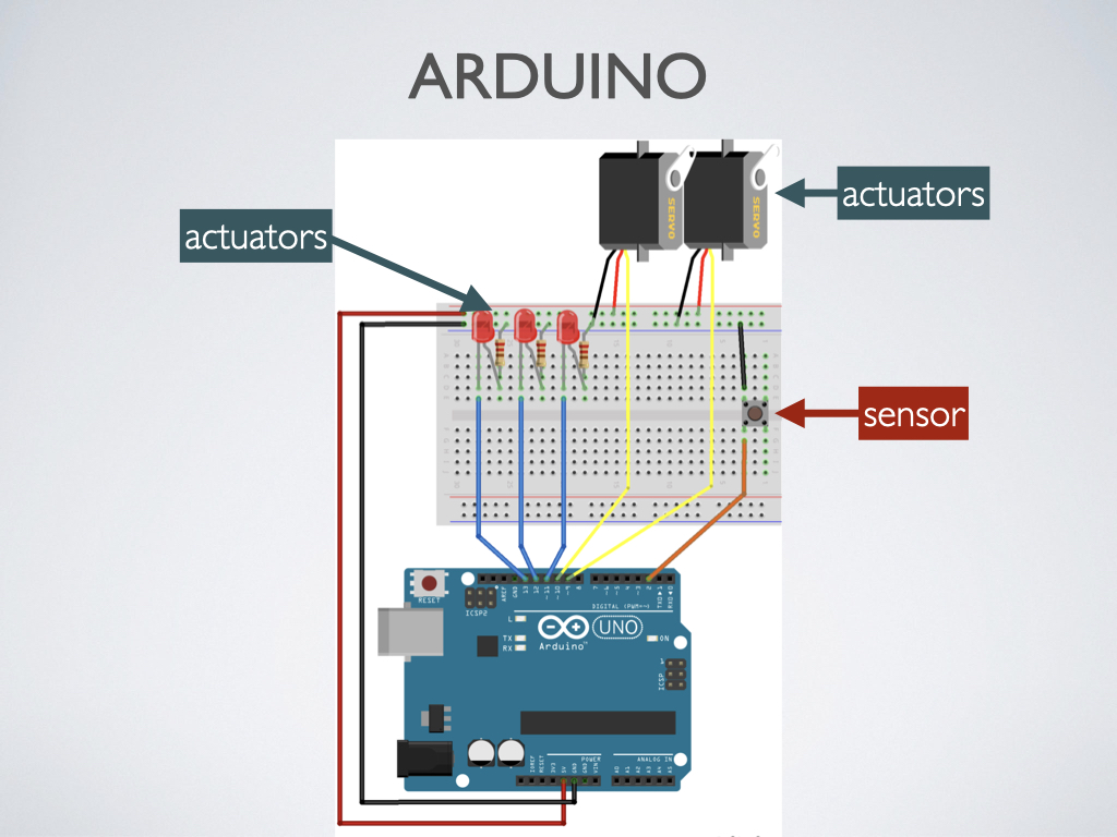
When creating circuits with an Arduino, you can prototype very quickly on a breadboard without needing to solder. On the Arduino, you have pins for connecting sensors (e.g. a button), which take in data from the world and convert it to a signal for the computer to understand. Actuators (e.g. LEDs to give light-based visual feedback, or servo motors to make something move) convert a signal from the computer and make something happen in the physical world. The sensors and actuators are controlled through voltage and code—
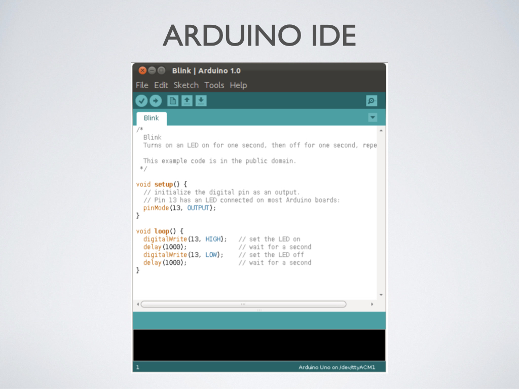
On the code side, writing for Arduino looks something like this. This is the Arduino IDE (Integrated Development Environment). It’s a code editor, compiler, and debugger all in one.
Now that you have some idea of how inputs are measured by sensors and can be converted, via Arduino hardware and code, to outputs that affect the real world by actuators, let’s go over your responses to the Assignment 8 readings—

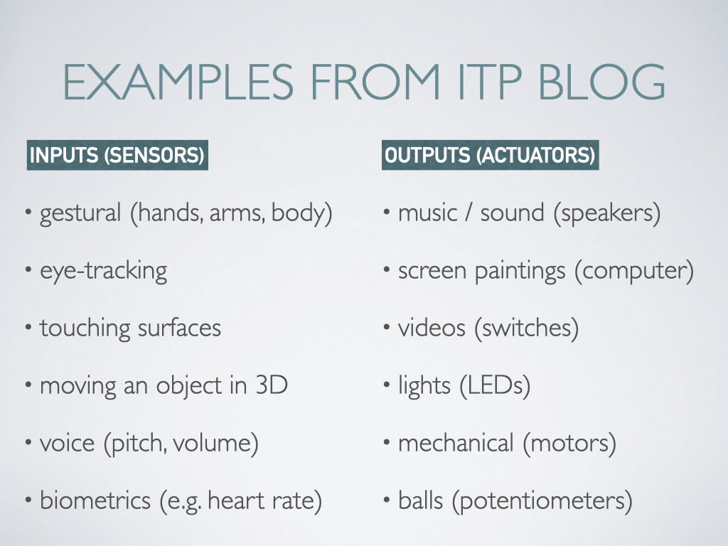
Pay attention to what author Tom Igoe said about what kinds of gestures are meaningful, sending someone’s presence versus their attention, and robotics versus physical computing. Here’s a breakdown of some types of inputs and outputs used in the projects that he mentioned—
With the wearable tech ideas mentioned in this Time Magazine article, think about the categories that were covered (fitness, mental health, productivity, social, navigation, safety), and what kinds of issues or questions need to be addressed (ethical, moral, security). Also think about the types of sensors that are required (biometrics, location, liquid, accelerometer)—

The third reading also covered wearables but had a more practical focus and included examples like the Sunu Band, meant to help the visually impaired via haptic feedback—

This reading mentioned important design considerations to keep in mind when coming up with a potential product solution—


Remember, whatever you design can have personality and humor, like Tomatan, the 18-pound wearable robot that feeds you tomatoes as you run when you press a switch—
Before Wednesday’s class, study the following set of slides for key info that will be on the short quiz, and also to note questions that you have—
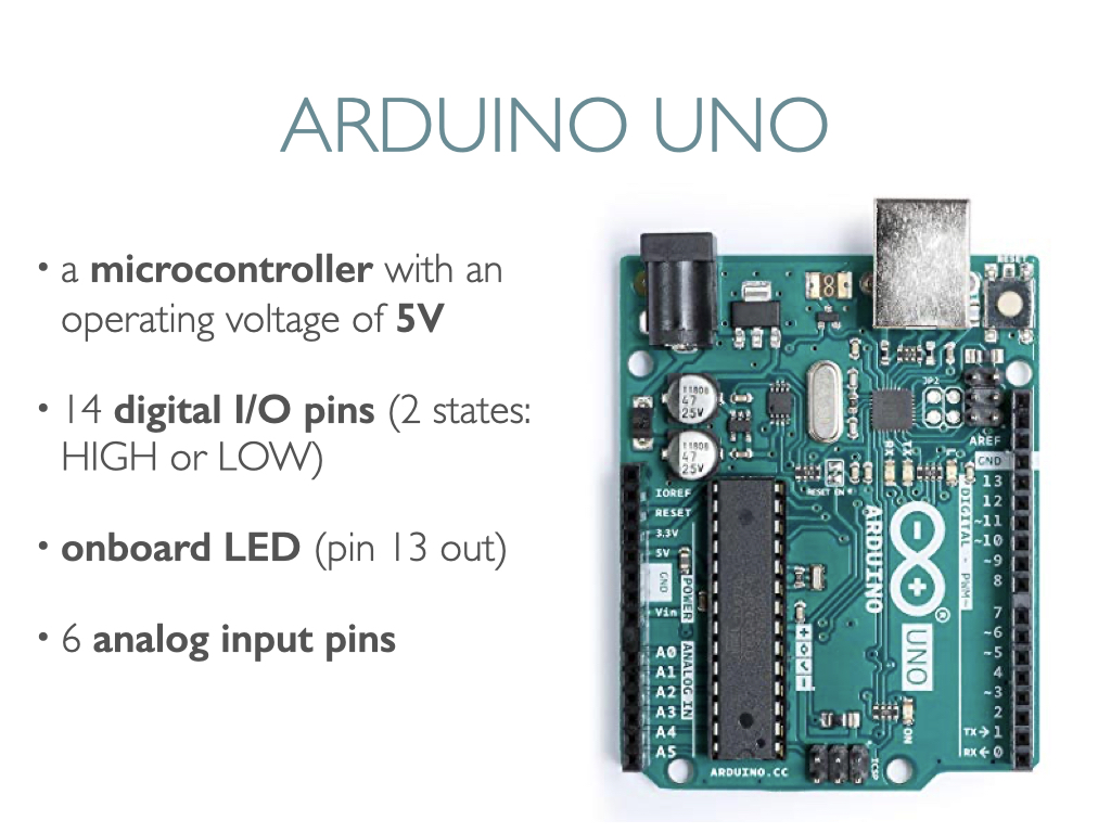
The Arduino Uno is a microcontroller, a standalone controller within embedded systems used for rapid prototyping in P-Comp. It has a USB connection and you can plug it in, or use a battery pack. There are 14 digital pins that can be used for input or output, and the code that controls those pins is like a Boolean variable with 2 states, in this case HIGH or LOW. When an LED is wired to one of these pins as an output, the pin can only perform two jobs: turning the LED on and turning the LED off. The onboard LED is great for troubleshooting, e.g. if that lights up and the LED that you wired doesn’t, it means something is wrong with your wiring or the component itself. This symbol ~ is for the pins that provide PWM output—Pulse-width modulation: a method of reducing the average power delivered by an electrical signal, by effectively chopping it up into discrete parts. The average value of voltage (and current ) fed to the load is controlled by turning the switch between supply and load on and off at a fast rate. On the other side, you’ll see 6 pins (A0-A5) that serve as inputs only for analog sensors, like a photocell that can measure the amount of light.
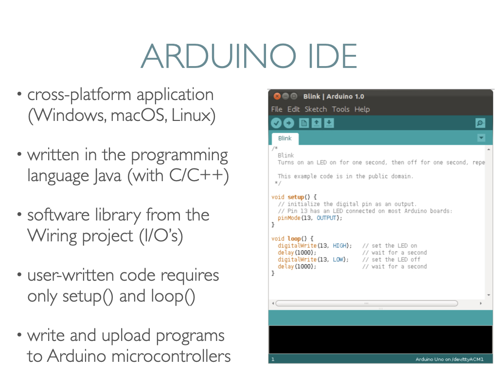
The source code for the Arduino IDE is released under the GNU General Public License, version 2. The Arduino IDE is written in Java and supports the languages C and C++ using special rules of code structuring. Included is a software library from the Wiring project, which provides many common input and output procedures. That means the code we write only requires two basic functions, for initilizing the program (void setup) and for running the program (void loop). (The program “avrdude” converts the executable code into a text file in hexadecimal encoding that is loaded into the Arduino board by a loader program in the board’s firmware.)
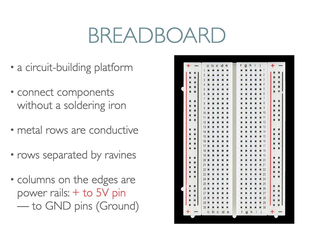
A breadboard is a circuit-building platform that allows you to connect multiple components and wires without using a soldering iron. The one pictured below has 2 power buses, 10 columns, and 30 rows, for a total of 400 tie-in points. The ravines are used for DIP IC’s (Dual in-line Package Integrated Circuits. With wires, you can connect anything in the black- column to the GND (ground) pin on the Arduino, and anything in the red+ column to the 5V pin, for example, in the power area on the Arduino.
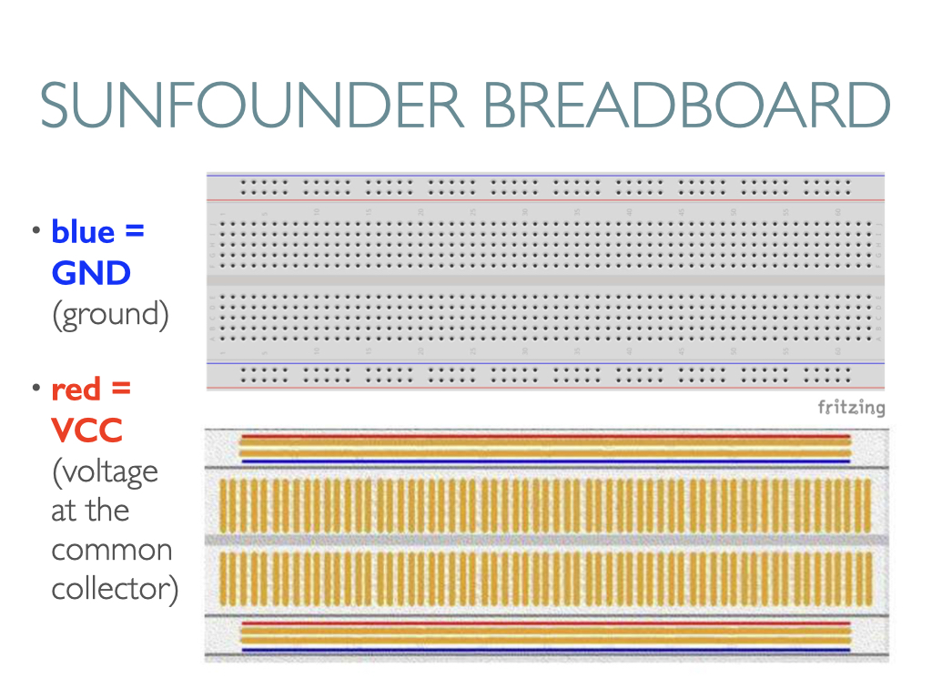
This is what a breadboard from Sunfounder looks like (they use blue instead of black), and you can also see how the rows and columns are connected underneath.
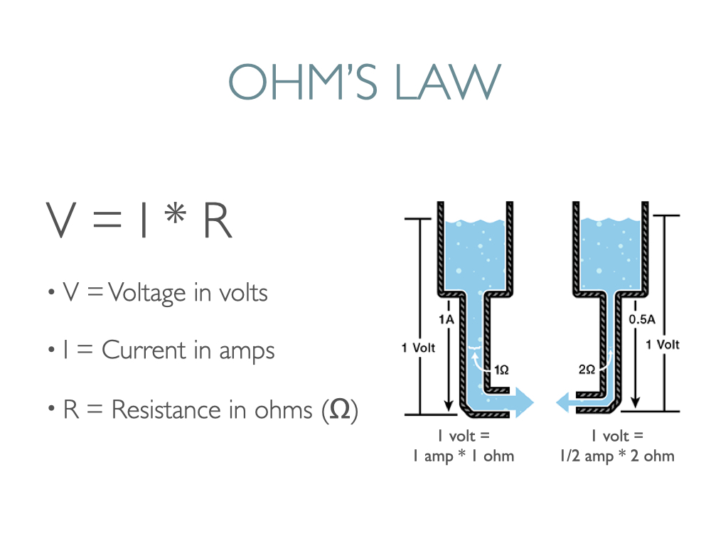
Electricity is the movement of electrons. Electrons create charge. Ohm’s law describes the relationship between the three key elements of electricity: voltage, resistance and current. This equation is what’s utilized to calculate resistor values in circuits so that one doesn’t overload a circuit with too much current.
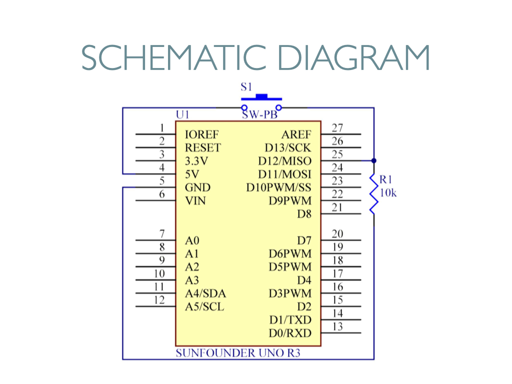
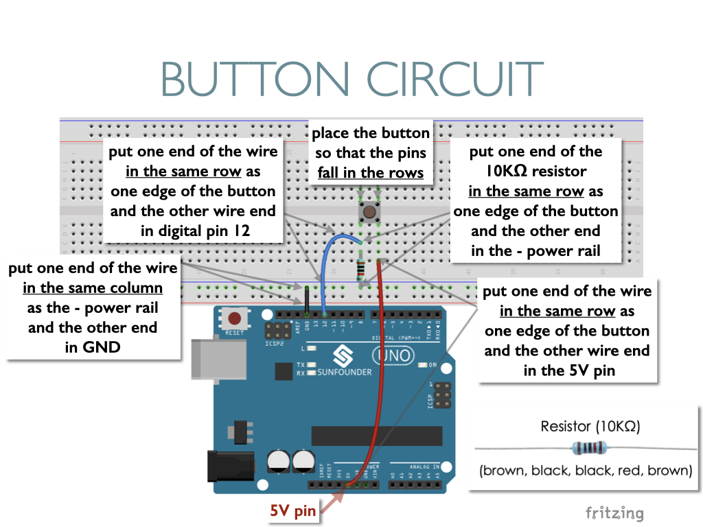
A schematic diagram illustrates the electric flow of a circuit. Below is one for a button, where one side goes to 5V and the other side meets a 10k resistor before going into ground.
Buttons are a common component used, usually used as switches to connect or break circuits.
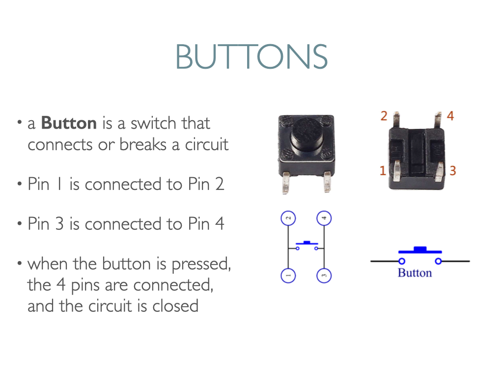
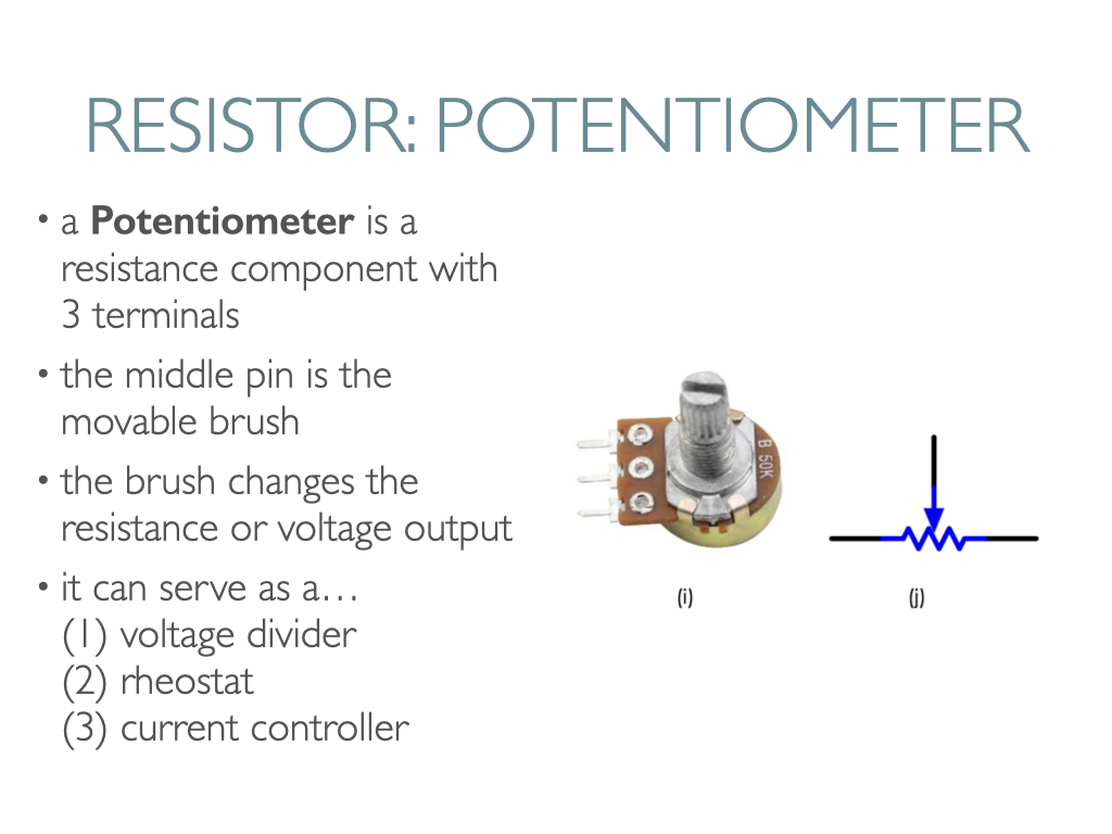
A resistor is an electronic element that can limit the branch current. A fixed resistor is one whose resistance can’t be changed, whereas the resistance of a potentiometer, or variable resistor, can be adjusted.
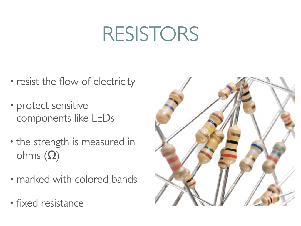
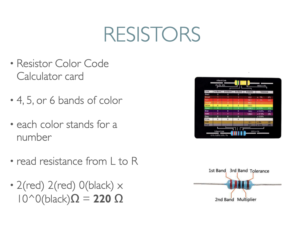
The Sunfounder kit should contain a Resistor Color Code Calculator card.
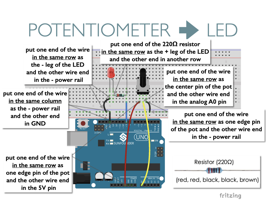
In a standard four band resistor, the first two bands indicate the two most-significant digits of the resistor’s value. The third band is a weight value, which multiplies the two significant digits by a power of ten. The final band indicates the tolerance of the resistor, which explains how much more or less the actual resistance of the resistor can be compared to what its nominal value is. Read the resistance from left to right. So for the one pictured below, the resistor value is 2(red) 2(red) 0(black) x 10^0(black) Ω = 220Ω where Ω means ohms. The permissible error is ± 1% (brown).
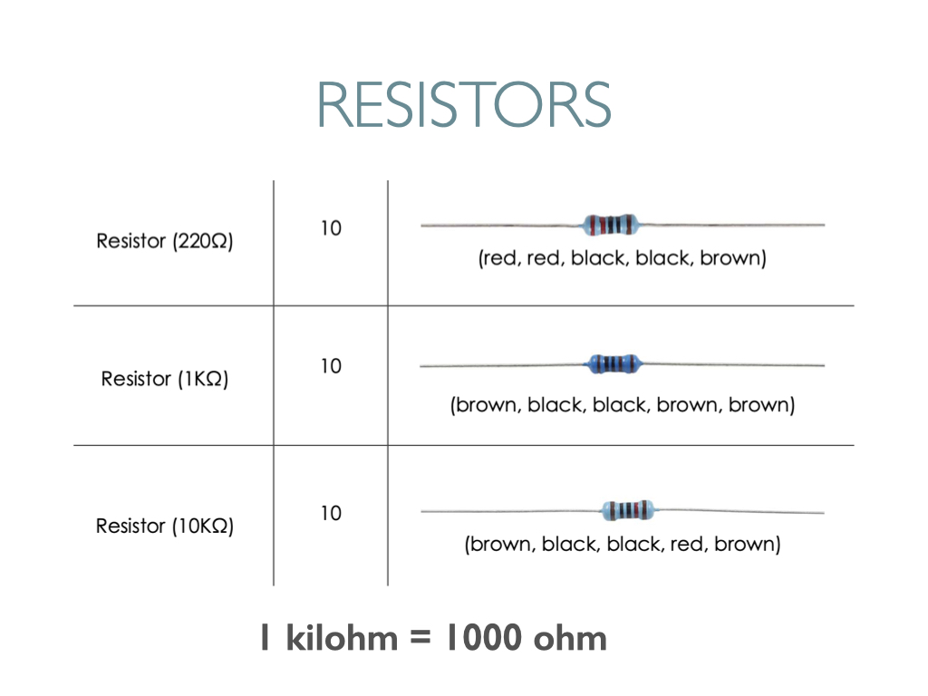
Your Sunfounder kit should contain 10 each of these three resistors: 220 ohm, 1 kiloohm (or kilohm or 1000 ohm), and 10 kiloohm (or kilohm or 10,000 ohm). It’s best to sort and label resistors clearly before beginning your circuits.
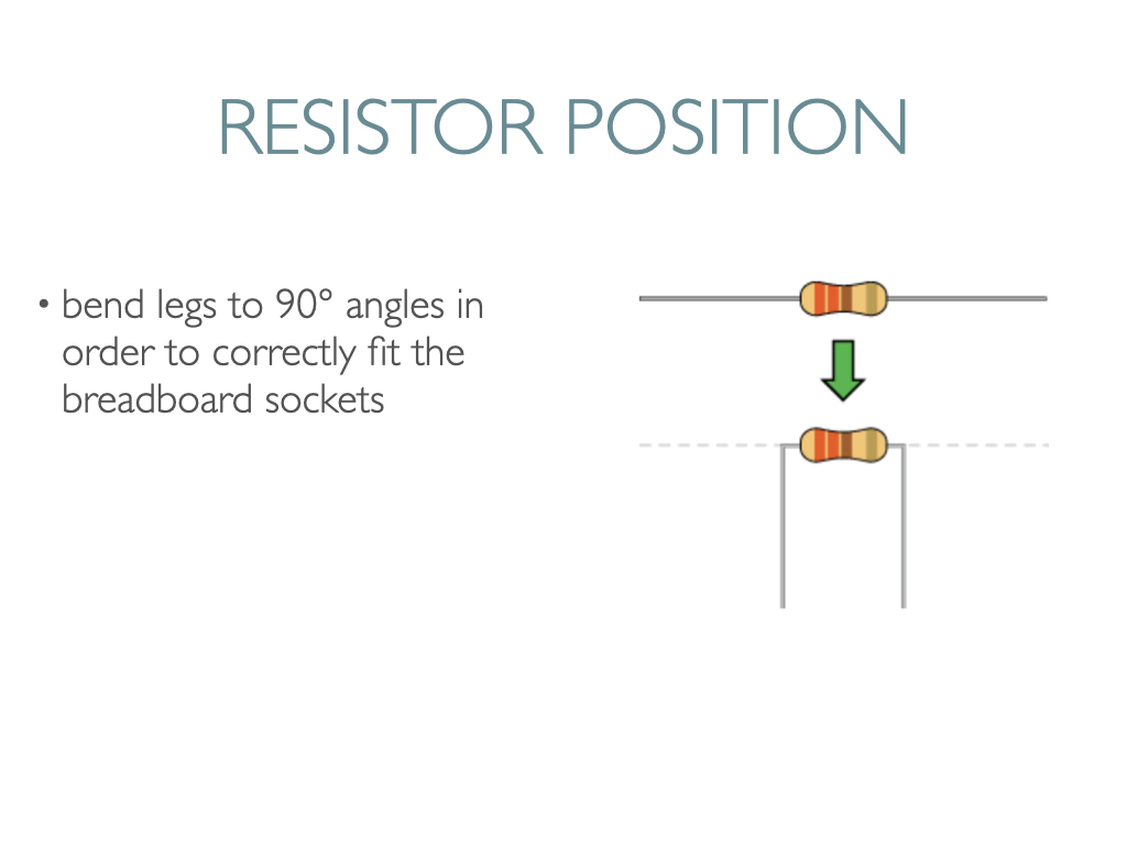
Components like resistors need to have their legs bent into 90° angles in order to fit most easily into the breadboard sockets.
Below is an annotated circuit diagram for Sunfounder’s button circuit that you can try if you have an Arduino kit—
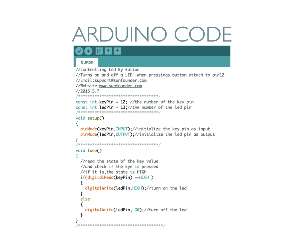
The corresponding code for this button circuit that lights up the onboard LED looks like this. Note the variables for the Arduino digital pins at the top using “const int.” The pinMode function assigns INPUT or OUTPUT to digital pins via the variables inside the setup block. Inside the loop block, you’ll see a familiar if/else statement that says if the keyPin input is “HIGH” then turn on the LED by setting the ledPin to “HIGH.” Otherwise turn it off by setting it to “LOW.”
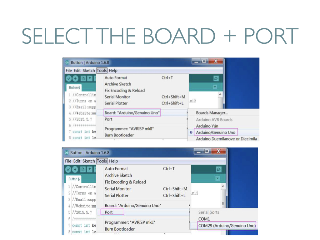
Before uploading code to the Arduino microcontroller, make sure you’ve selected the correct BOARD and PORT.
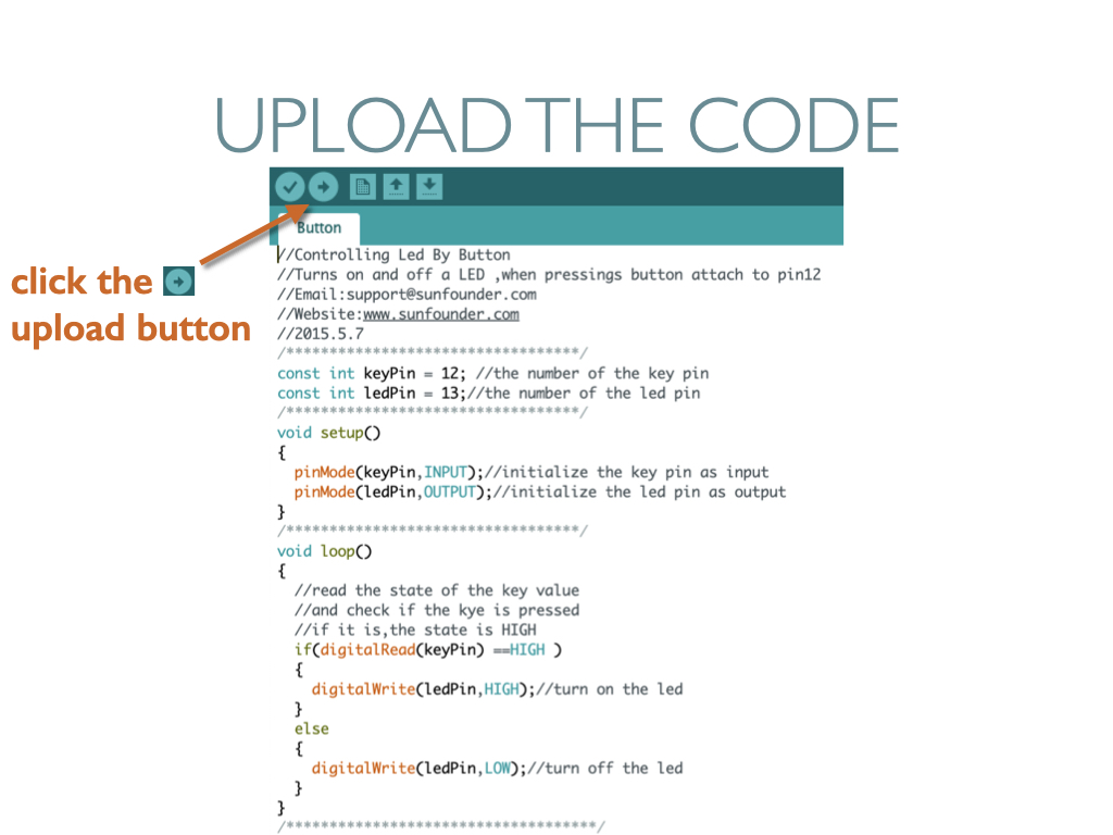
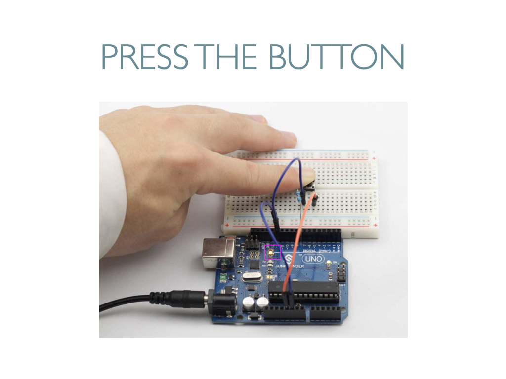
If your circuit is correct, then pressing the button that you wired on the breadboard will light up the onboard LED.
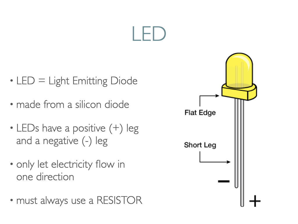
The next step is to wire up an LED component. An LED has polarity, meaning electricity can only flow through it in one direction. Components like resistors do not have polarity, by contrast.
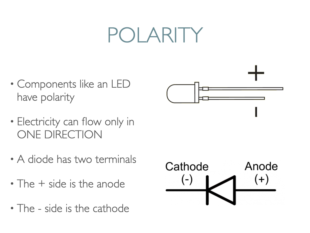
LEDs can burn out if too much electricity flows through them, so you should always use a resistor to limit the current when you wire an LED into a circuit.
Potentiometers (called “pots” for short) are not polarized. You can attach either of the outside pins to 5V or GND. However, the values you get out of the pot/trimpot will change based on which pin is 5V and which is GND.
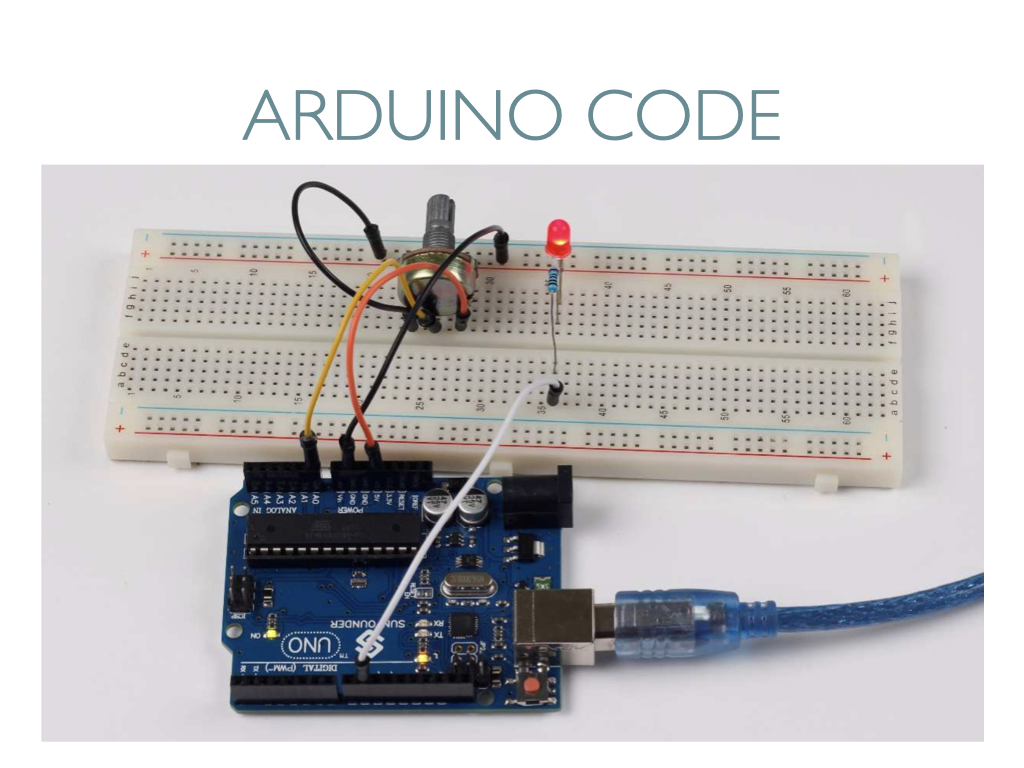
Below is an annotated circuit diagram for using a potentiometer to make an LED brighter or dimmer. A potentiometer is an analog electronic component. The data state of analog signals is linear, for example, from 1 to 1000, so the signal value changes over time instead of indicating an exact number. Sensors you can use with analog pins include ones that measure light intensity, humidity, and temperature, for example.
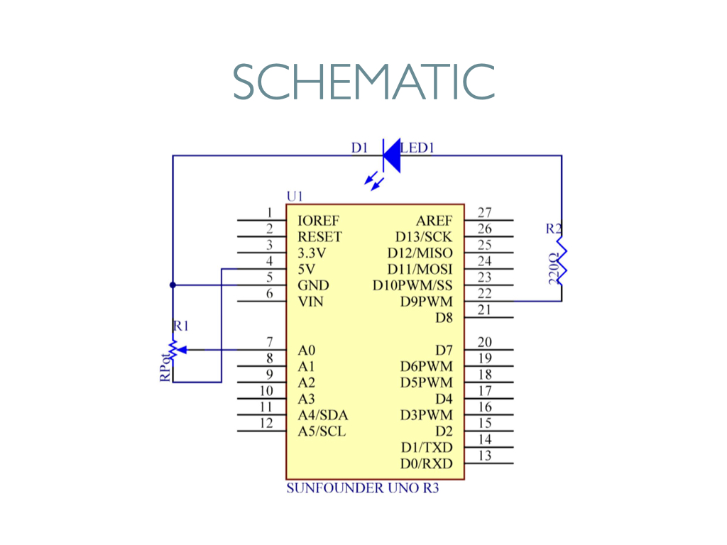
In the schematic below, you can see that the pot is connected to pin A0 of the SunFounder Uno board.
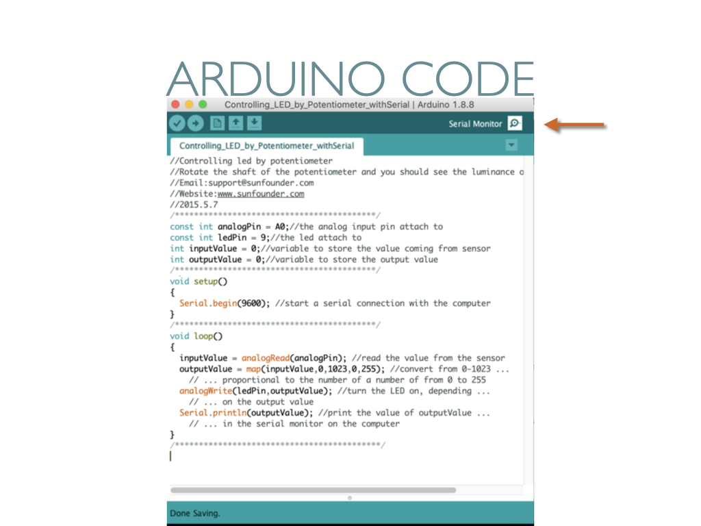
Below is the corresponding code. I added the Serial.begin code from SparkFun’s Potentiometer circuit tutorial so that you can see the numeric pot values via the Serial Monitor, which you open by clicking on the icon that the arrow is pointing to.
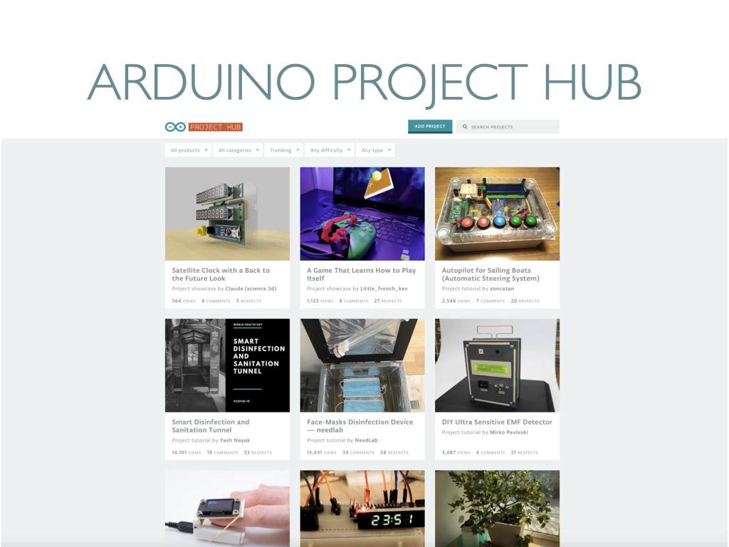
For more inspiration and tutorials, check out the Arduino Project Hub—
We’ll begin Project 3 at the start of Wednesday’s class.
Print this page


Leave a Reply