Preview
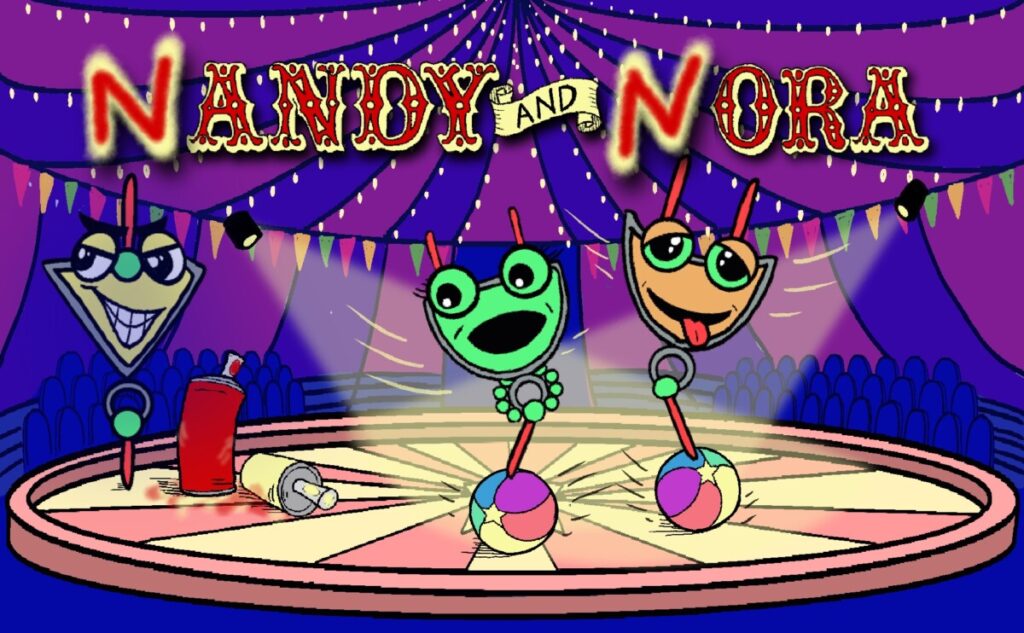
So far we have learned about 3 logic gates: NOT, AND, and OR. In this episode, we’ll learn about how to negate the AND and OR gates using the NOT gate. Nandy the NAND gate and Nora the NOR gate, illustrated above, are the opposites of Andy and Ora from Episode 2!
Play
NAND
First, we’ll build a NAND gate. Drag the gates on the right into the empty spots in the diagram on the right to create a logic gate that represents:
AND followed by NOT
This means that the output of the AND gate becomes the input for the NOT gate.
How would you describe in words what this gate does to pairs of different inputs? What if the inputs are the same as one another? What if the inputs are different? Play with the gate below to see what happens with different pairs of inputs.
Hint: if the interactive tool does not work on your device, you can watch this video.
The gate above is called the NAND gate. NAND represents NOT-AND (here, this means AND first, followed by NOT). Notice the symbol used to represent the NAND gate. It looks a lot like the symbol for the AND gate, but it has a little circle on its output, just like the symbol for the NOT gate does! We like to think of the symbol for the NAND gate as being a combination of the symbols for the AND gate and the NOT gate.
NOR
Next, we’ll build a NOR gate. Drag the gates on the right into the empty spots in the diagram on the right to create a logic gate that represents:
OR followed by NOT
How would you describe in words what this gate does to pairs of different inputs? What if the inputs are the same as one another? What if the inputs are different? Play with the gate below to see what happens with different pairs of inputs.
Hint: if the interactive tool does not work on your device, you can watch this video
The gate above is called the NOR gate. NOR represents NOT-OR (compare this to how NAND represents NOT-AND). Notice again that the symbol used to represent the NAND gate looks like the symbol for the OR gate, but it has a little circle on its output, just like the symbols for the NOT gate and the NAND gate do! We like to think of the symbol for the NOR gate as being a combination of the symbols for the OR gate and the NOT gate.
Progress
NAND
Recall that the Boolean expression for NOT A is $A’$ and that the Boolean expression for A AND B is $A \cdot B$. Putting these expressions together, we get that the Boolean expression for A NAND B is $(A \cdot B)’$.
To get the truth table for NAND, we just ignore the column for the intermediate node (node 1)!
Something to notice is that in the Boolean algebra expression for NAND, we really see the notation for two gates because we form $A \cdot B$ and then negate it to get $(A \cdot B)’$. We will always use this notation for NAND when we’re typing. In the logic diagram, we usually represent this operation with the single NAND gate (like in the interactive diagram at the beginning of this episode) and in the corresponding truth table we may see an intermediate column like we did in the exercise or we may just see the input and output columns.
NOR
Recall that the Boolean expression for A OR B is $A +B$. Putting this together with the notation for NOT, we get that the Boolean expression for A NOR B is $(A +B)’$.
To get the truth table for NOR, we just ignore the column for the intermediate node (node 1)!
Again, the Boolean expression for A NOR B combines the notation with OR and NOT so we will always type A NOR B as $(A + B)’$. The logic diagram symbol usually shows just one gate and the truth table may show an intermediate column or it may not.
Practice
Now you’ve learned 3 representations (diagram symbol, truth table, and Boolean expression) of 5 different logic gates (NOT, AND, OR, NAND, and NOR). This means you’ve learned 15 different representations! Check which representations you remember by playing the flashcard game below.


