Preview
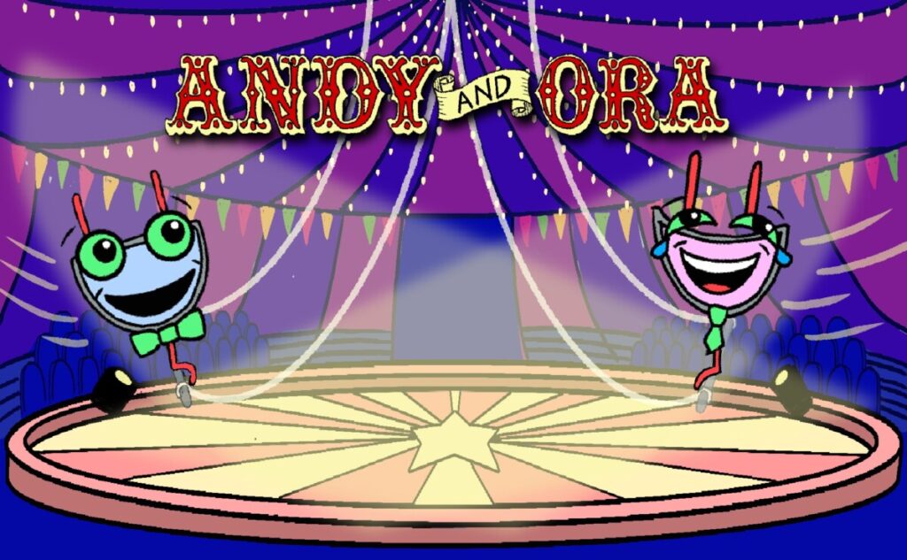
In this episode, we’ll meet two more of The Great Gates: Andy the AND gate and Ora the OR gate, illustrated above. While the Notty the NOT gate from Episode 1 took one input and produced one output, both Andy and Ora each take two inputs and produce one output. Each of these two new gates will have three different representations:
- a logic diagram symbol,
- a truth table, and
- a Boolean expression.
Play
Play with the AND gate and the OR gate by clicking on the inputs in the logic diagrams below (remember: our inputs are on the left and our outputs are on the right) and consider the following questions:
- What is the same about the symbols representing AND and OR and what is different?
- For each of these gates, what happens to the output as you change the inputs How would you organize this information in a truth table? How many rows should it have?
- How would the truth table for AND be the same as or different from the truth table for OR?
AND
Hint: if the interactive tool does not work on your device, you can watch this video.
OR
Hint: if the interactive tool does not work on your device, you can watch this video.
How would you describe the symbols representing the AND gate and the OR gate? How are the symbols the same? How are they different?
Progress
AND
You probably noticed that in order for the output of the AND gate to be 1, both inputs had to be 1. We’ll fill in this information in the truth tables below.
Recall from Episode 1 that we used the Boolean expression A’ to represent NOT A. The AND gate has two inputs, so we will call one of them A and the other one B. The Boolean expression to represent A AND B is:
$A \cdot B$.
Notice that the Boolean expression for A AND B looks an awful lot like the familiar-looking algebraic expression $A \times B$; the product of two variables. This is not a coincidence! The AND gate and the multiplication operation have some things in common, which we will see in the truth tables below and again later as part of a system called Boolean algebra.
In the following exercise, we’ll need to type answers like “A AND B“. We can type this in three different ways:
- A and B (“and” must be lower case),
- A*B (the usual Boolean representation, which looks like $A \cdot B$), or
- AB (if A and B were regular algebraic variables like the ones you see in your math class, AB would mean A times B… the Boolean algebra version of times works the same way).
*Please note that the following exercise contains a small typographical error: you should complete the truth table for the AND gate as pictured (not an OR gate). We are working to fix this typo!
OR
You probably noticed when you played with the logic diagram above that in order for the output of the OR gate to be 1, either one input or the other input (or both inputs) had to be 1.
The Boolean expression to represent A OR B is:
$A+B$
Notice that the Boolean expression for A AND B looks an awful lot like the familiar-looking algebraic expression for the sum of two variables. This is also not a coincidence! The OR gate and the addition operation have some things in common, which we’ll see in the truth tables below.
In the following exercise, we’ll need to type answers like “A OR B“. We can type this in two different ways:
- A or B (“or” must be lower case), or
- A+B (the usual Boolean representation).
Practice
Now you’ve learned 3 representations (diagram symbol, truth table, and Boolean expression) of 3 different logic gates (NOT, AND, and OR). This means you’ve learned 9 different representations! Check which representations you remember by playing the flashcard game below.


