05/11/2015
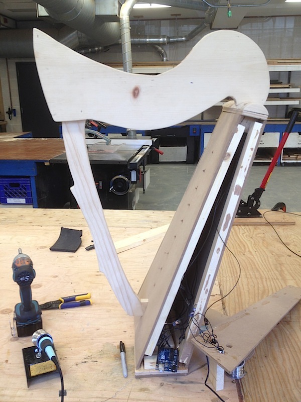
Over the weekend it became clear to me that I will not be able to make a plexiglass enclosure for my harp. First of all, the CNC router on the first floor is not working; secondly, I simply don’t have enough time to build a new enclosure. This being said, I decided to enhance the overall look of the prototype a little bit, and present it as is. I used some wood finish for the neck and pillow, and painted everything else gray.

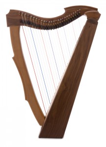
Below is a picture of the final product:
 I will present my project to faculty on Friday, so I still have to do some paperwork and nice schematics. But at least the physical device is finished (although not entirely as intended).
05/09/2015
Tried white tack instead of Velcro – the result is a little bit better, but still not perfect. Some modules don’t want to stay in place for a long time.
 Below is the video of my friend Sharon playing harp in the sound lab (thanks Sharon!). Bottom resistors are still misaligned:
05/08/2015
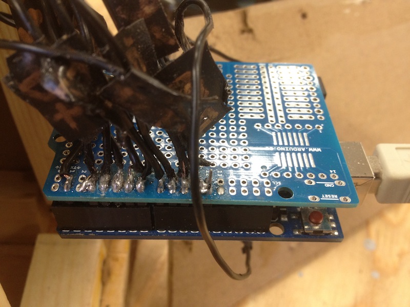
Got some pin headers for the protoshield and decided to finish soldering.
 Below is a final shield attached to the Arduino. Looks disastrous, but works fine.
05/06/2015
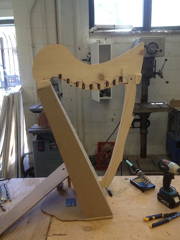
First test of the entire system. Some pointers are still not aligned, and the wires are not soldered into the proto shield (just inserted into the pin headers)
05/04/2015
The hardest thing is to align laser modules and photo resistors together and to KEEP IT ALIGNED, which looks impossible to me. Velcro doesn’t really work, so I will try something else, probably white tack or hot glue.
05/02/2015
Made first attempt to put everything together. Drilled nine 1/4″ holes in the enclosure’s “sound box” and inserted photo resistors. Put the Arduino inside the sound box and connected all the wires. I still have to solder everything to the Arduino protoshield, but will do it later.
 Figured out the placement and dimensions of the holes for plugs. Currently I have Power Out, MIDI In, and USB B In. Put everything in place and secured the enclosure using machine screws.
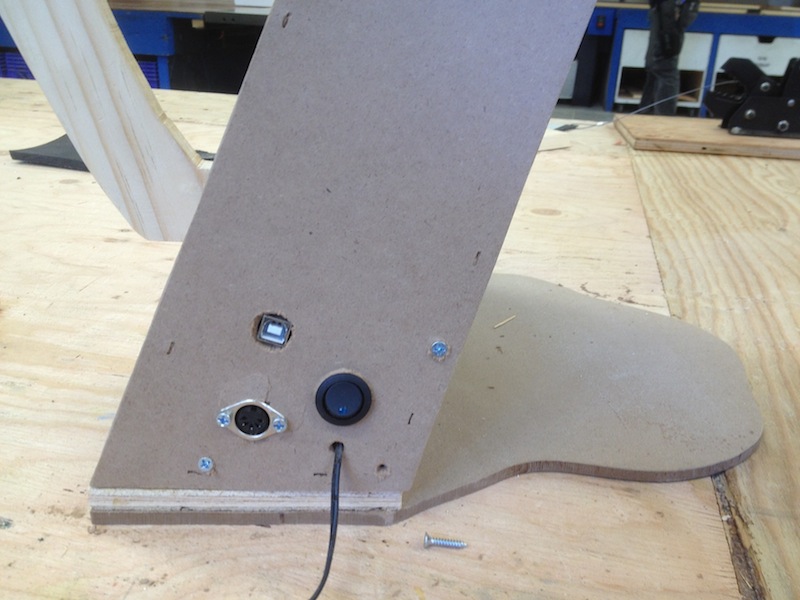 Found an old 5V power supply in V014, and used it to power up the lasers.
04/30/2015
Asked JR about using a fog machine during final presentation. Unfortunately, it is impossible, because of the fire alarm and sprinkler system in the sound lab.
04/29/2015
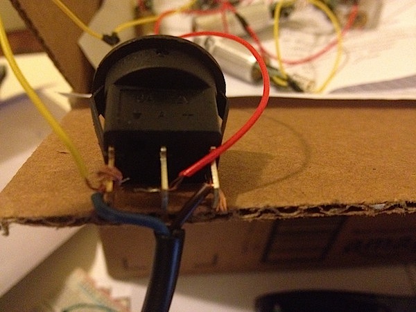
Breadboarded new circuit, added a power button, and tested everything using just the Arduino 5V power. Everything works good. Will look for an appropriate power supply tomorrow.
04/27/2015
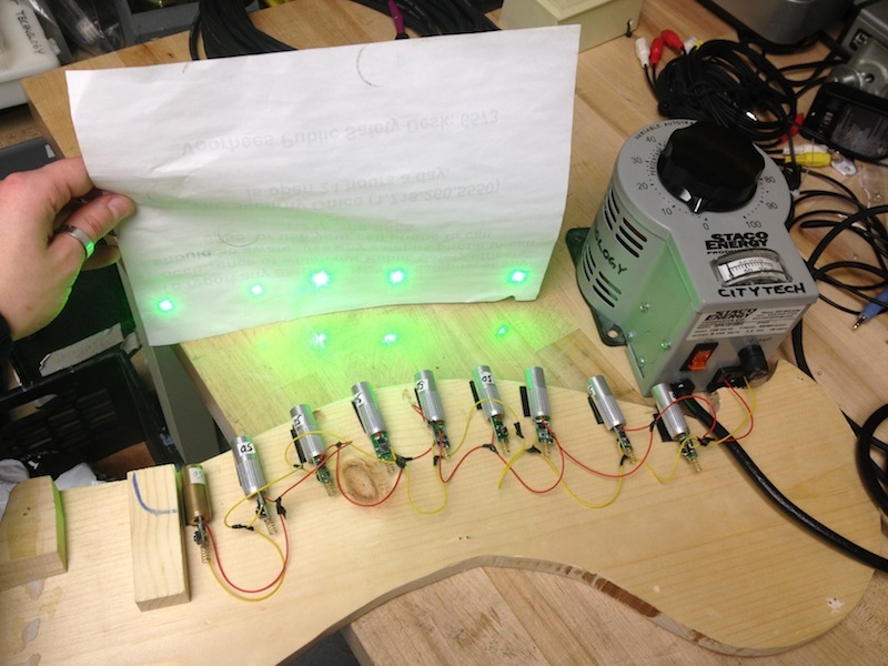
Found variable autotransformer in V014, and hooked it up to my circuit.

Turned the voltage knob to 3V indicator – 5 out of 9 laser modules were working. Decided to turn the knob a little bit more (~6V) – 7 pointers were up. Got overexcited and kept turning the knob until everything was up and bright. Decided to make a small video of the working circuit, but suddenly realized that not all the lasers are on anymore. Turned the knob back to 3V and tested each module separately – 4 out of 9 green modules were dead.
After being very sad for a couple of minutes, decided to forget about green lasers and move on using cheap low-power red pointers. Now I have to do everything all over again: assemble, test and solder the circuit, and then find a reliable power supply (this time regular 5V PS should work fine).
04/24/2015
Talked to Professor Huntington and Professor Patton about the power supply issues, and found out that my 12V to 3V step down converter is unreliable, because it can not provide steady amperage. Professor Patton suggested to find a way of multiplexing the amperage. Professor Huntington told me that there is a variable voltage power supply in one of the closets in V014, and I can use this instead. I will certainly try it on Monday, and hope it will work.
04/22/2015
Finally got my new 12V to 3V step down converter! Very carefully wired it up with the 12V power supply and laser circuit, checked all connections, plugged it in and… it doesn’t work. And I can’t understand why. The result is below:
It is hard to see, but only 4 laser modules are on: 2 pretty bright and two very dimmed. For some reason, the circuit acts like it is wired in series and not in parallel.
Decided to desolder 3V converter and try 12V power supply on its own again. For approximately 1 minute everything was on and very bright, but then I noticed smoke coming out of the laser modules, and quickly unplugged everything. Luckily, all laser modules are still in working condition. I will talk to Professor Baker tomorrow, and hopefully we will be able to find a solution.
04/20/2015
Decided to try to integrate the circuit with the enclosure. Took the enclosure apart (noticing a lot of drawbacks in the design). Spent more than 2 hours trying to determine how to secure laser modules in the neck of the harp with the possibility of a quick adjustment. First, I was planning to use something like a plumber strap or a rubber belt (just staple small pieces directly to the wood and put laser modules in the “pockets”). Then, after talking to people in the shop, found a much better solution – 3M Dual Lock Reclosable Fasteners . Works pretty good so far.
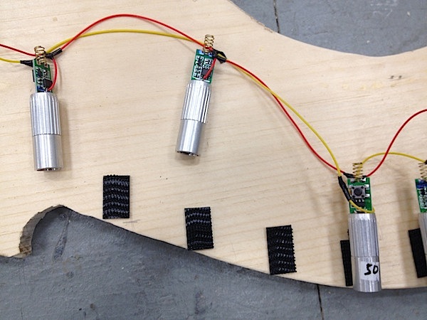
Also drilled 1/4″ holes in the “sound box” and inserted photo-resistors in there. It is already quite clear that it will be very hard to align laser modules with photo-resistors at a steep angle. Probably, some modifications in the enclosure design will be needed.
04/19/2015
Assembled the Arduino/Photo-resistors circuit. Wired photo-resistors as in-series voltage dividers with 4.7K resistors. Labeled everything and connected to the appropriate Arduino digital pins. Hooked up MIDI jack to the Tx, 5V and GND pins.
The result is below. Looks pretty disastrous, but works fine:
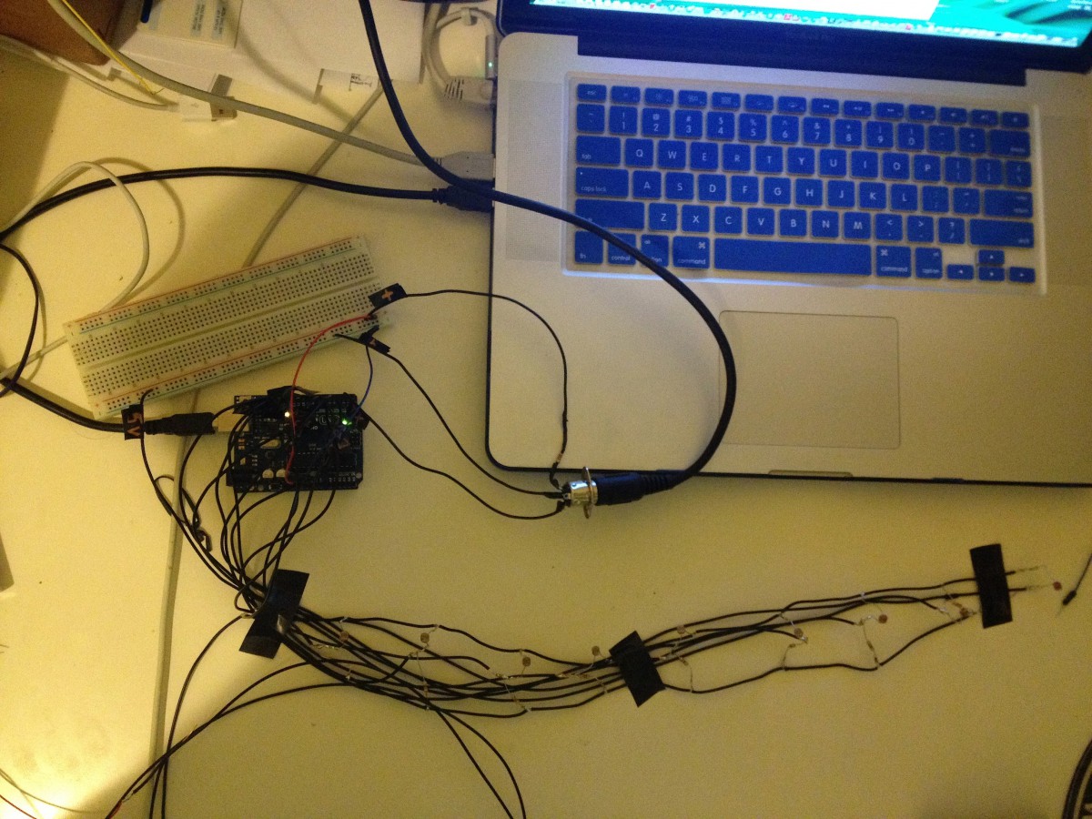
 The video is showing my test of the circuit with one green laser. It’s hard to quickly align the beam with photo-resistors. Also, it’s very hard to make a video while aligning. There are 9 photo-resistors: the first and the last one are Octave Up and Octave Down, and the remaining seven are notes:
Once again, the code I’m currently using is not mine. It can be found on the following web site: open-source-energy.org
04/16/2015
Added a power button to the circuit and tested it – works great.
04/14/2015
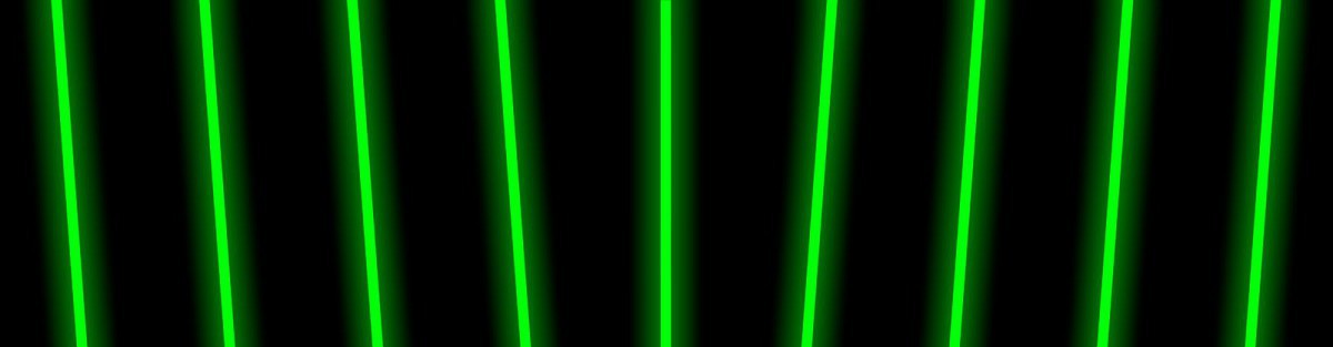
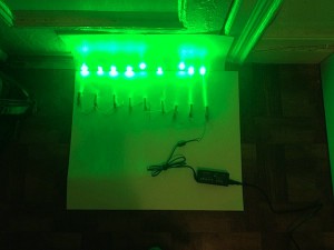
Decided to risk and do a quick test of the laser modules circuit with a 12V power supply which I currently have:
 Tested it just for a couple of seconds. Because of the excessive voltage (12V instead of 3V) all modules are extremely bright and could easily burn out. It’s much better to wait for a new step down converter to come.
04/12/2015
Both power supplies have finally arrived:
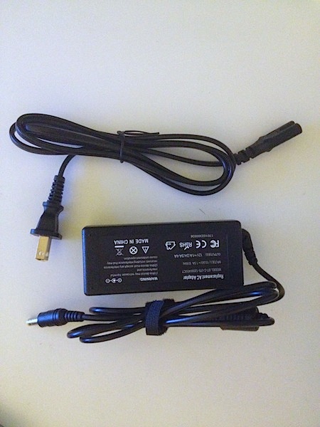
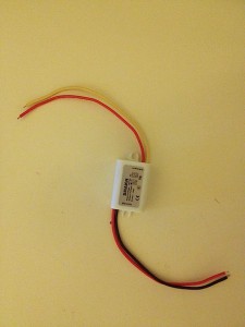
Wired them together, decided to test the circuit and … immediately blew up the step down converter (with some smoke and unpleasant smell). After a quick examination found the dumbest possible error – swapped wires. Ordered a new step down power supply from Amazon.
04/09/2015
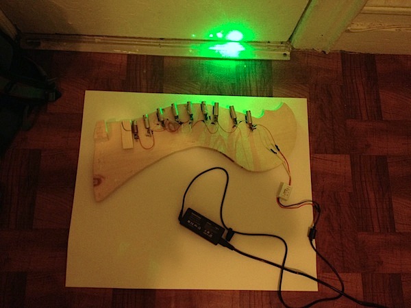
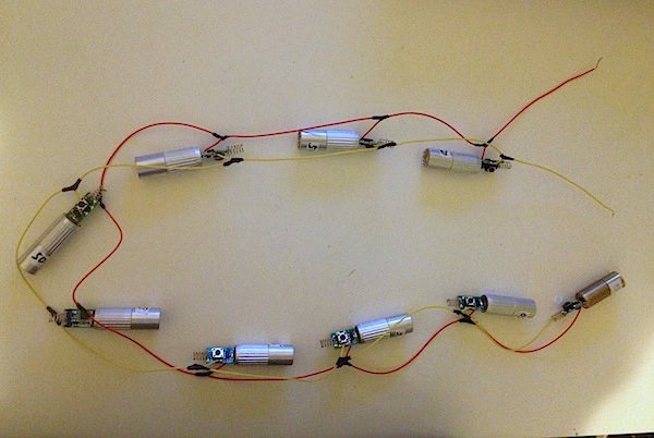
While waiting for the power supplies, decided to get the entire 9 laser modules circuit ready. Wired everything in parallel, soldered the connections and put some electrical tape on top. Below is the circuit without a power supply:
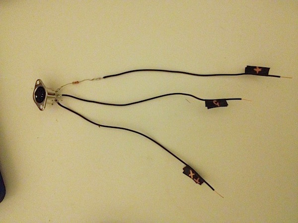
 Also, soldered wires and a 220Ω resistor to the MIDI jack. Labeled every connection point:
04/03/2015
Got some answers to my questions at the Laser Pointer Forums. Looks like my concept might work! Ordered a 12V 3A power supply and a 12V step down to 3V converter.
04/02/2015
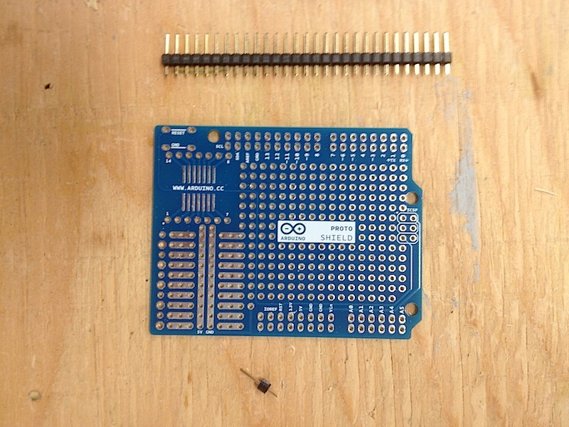
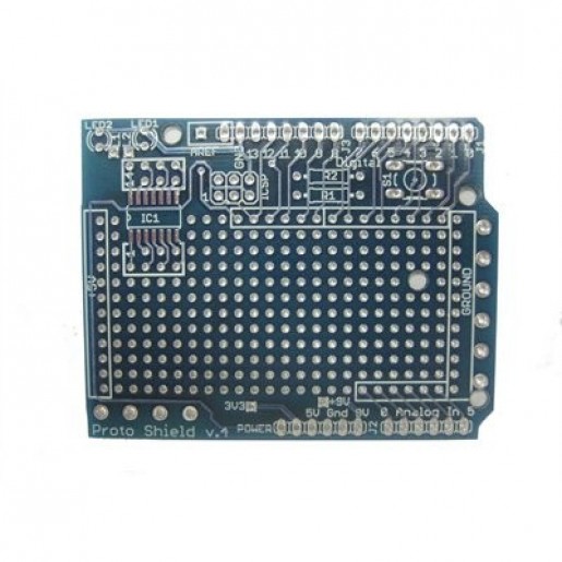
Ordered two (just in case) bare Arduino Proto Shields from RobotShop.
04/01/2015
Finished reading Simon Monk’s “Make Your Own PCBs With EAGLE”, and found it fascinating. Learned how to create nice schematics and board layouts for custom PCBs, and even how to make my own libraries of parts and create Gerber files for PCB mass production. Decided to immediately apply acquired knowledge to the current project and started prototyping. Even found a web site where one can upload his or her designs (Gerber files) and get 10 professionally manufactured PCBs for just $10 (which is much cheaper and better looking than an etched homemade board).
To my great disappointment, after approximately 30 min into schematics, I realized that I don’t need a PCB… All I need is a bare Arduino prototyping shield, which will allow me to solder directly into it, instead of screwing up the Arduino. After a quick google search I found out that this shield not only does already exist but also can be ordered from RobotShop for just $3.27(!) Even though it turned out that I don’t need a custom PCB, I will make a nice schematics in EAGLE anyway, just for neatness of the final presentation.
03/31/2015
Did some math in order to calculate total voltage, amperage and resistance for the laser modules circuit. I’m using nine 50mW lasers 3V 280mA each. When wired in parallel, the voltage will stay the same (3V), while current will be additive (.28A x 9 lasers = 2.52A). As for resistance, Ohm’s law gives 10.71Ω for every laser module (3V/0.28A), and since there going to be 9 lasers wired in parallel, total resistance will be approximately 0.84Ω. It looks like I don’t need any resistors at all between laser modules and power supply.
After some research, I discovered that it is sort of impossible to find a 3V 3A power supply. So my plan is to use 12V 3A PS such as this in conjunction with a step down power supply module such as this (just to solder them together). In (my) theory this will give me a constant voltage of 3V 3A.
Because I wasn’t sure if all this is at all possible, I decided to ask experts, and registered at the Laser Pointer Forums web site. Hopefully I’m going to get some answers in the near future!
03/25/2015
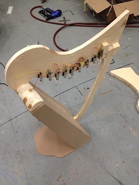
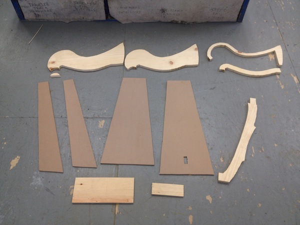
Started assembling the enclosure. Found out that I need additional pieces of 1x in order to put the “sound box” parts together:

Glued and stapled everything, then attached to the base. Glued and stapled curved pieces to get a shallow neck:
Below is the picture of the final (as of now) enclosure prototype:
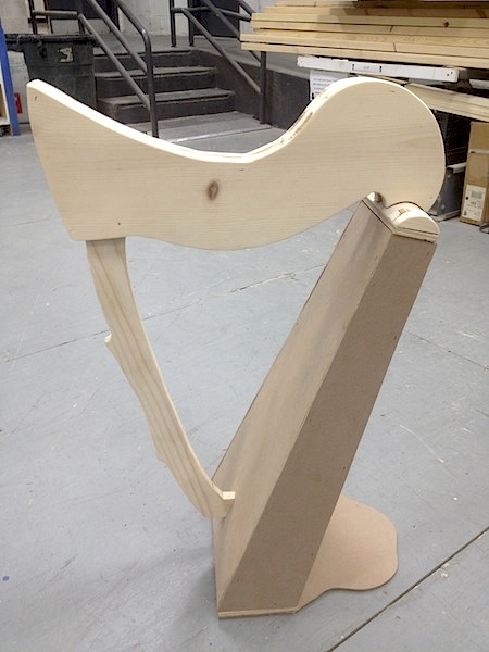
Noticed some minor drawbacks in the design, and will correct it later. Also, added a small “stand” piece, because the harp was top heavy and was tipping over. Still need to figure out how to incorporate laser modules and photo diodes into the design, how to align everything and make it easily accessible, where to put buttons and jacks.
Also, met with Professor Baker and outlined further actions. The circuit is essential and should be taken care of over the next week. I will wire some batteries for the laser modules in parallel, and see how it works. I will also finally build the entire circuit.
03/23/2015
Decided to learn how to create a 3D model of my harp using Autodesk Inventor (for presentation purposes). Started reading a book “Mastering Autodesk Inventor 2015” by Curtis Waguespack.
03/21/2015
Installed EAGLE Freeware version. Started reading Simon Monk’s “Make Your Own PCBs With EAGLE”, and was able to prototype simple 555 timer flasher circuit board based on the example from the book. Hopefully, soon will be able to make a laser harp PCB.
03/19/2015
Cut rectangular pieces using table and radial arm saws, and angular “sound box” parts on a jigsaw. Almost everything is cut and ready to be assembled.
Used 1/2″ plywood for the base and the top of the sound box, and 1/4 MDF for faces and sides.
03/17/2015
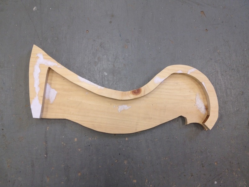
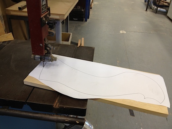
Started building the enclosure prototype. Printed out drawings to scale, glued them directly to the lumber, and cut out curved pieces using band saw. I’m currently using 1x SPF for curves, but later will switch to hardwood:
03/15/2015
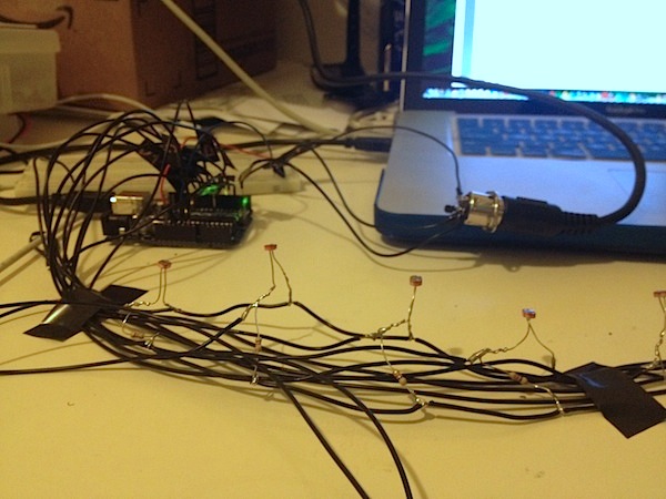
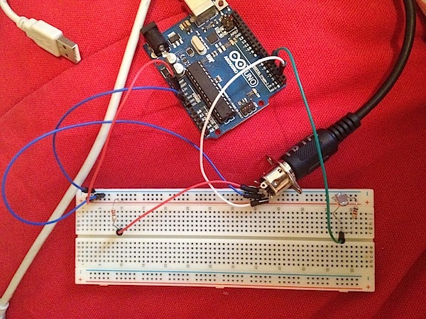
Put together a circuit with two green lasers and two photo-resistors. Photo-resistors are wired in series with 5.1K resistors:

Here is a picture of the setup (later I will make a schematic):
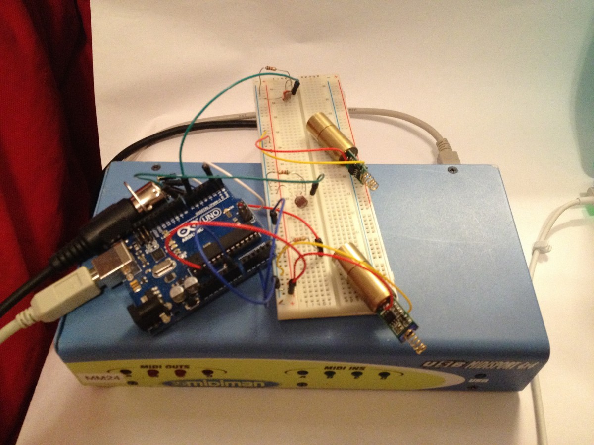
I used the code found on this web site: open-source-energy.org, so all credits go to mnsman‘s son, who wrote it. Below is the video of the first test. As of now, I only have two green laser modules, and I decided to test them first. In the next couple of days I will set up the entire circuit using red laser modules, which I have plenty:
Although everything seems to work, green lasers become very hot relatively fast and then start to dim out. Probably I will need some kind of a fan to cool them down, unless it’s a wiring problem. Also, besides the notes, an unwanted ambient sound is sometimes produced. I have to figure out the reason for this.
03/14/2015
MIDI jack and other components have finally arrived, so now I have an opportunity to assemble the entire circuit. After messing around with MIDI devices that I have, I found out that the keyboard is absolutely unnecessary – the Midiman MIDI interface connected to the laptop via USB is completely enough. My current signal path diagram looks as follows:
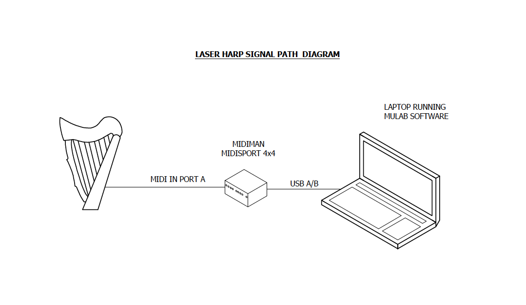 MIDI jack from the Arduino is connected to the MIDI In Port A of the Midiman interface. The interface itself is hooked up to the laptop running MuLab software via USB A/B cable.
Wired MIDI jack according to the pinout: Pin 2 – Ground, Pin 4 – 5V (through 220Ω resistor), Pin 5 – Tx.
03/11/2015
Here are some specifications (although, unfortunately not data sheets) for the Green Modules:
Working Temperature +15 ~+35 centigrade
And for the Red Modules:
Technical Information
Laser Dot Diode Module
Condition: New
Output Power: 5mW
Wavelength: 650nm
Working Voltage: 5v
Operating Current: less than 40 mA
Laser Shape: Dot
Working temperature: -10 ~40
Housing: Copper
03/10/2015
Met with Professor Baker and discussed power requirements for different laser modules, PCB manufacturing and design of physical structures. I have to find data sheets for both green and red lasers that I already have, in order to determine how much current will be drawn. Also, we will have another meeting next week, during which we will test the circuit.
03/8/2015
Found and ordered an interesting book by Simon Monk, titled “Make Your Own PCBs With EAGLE”. Now I definitely will use EagleCAD for making a custom PCB.
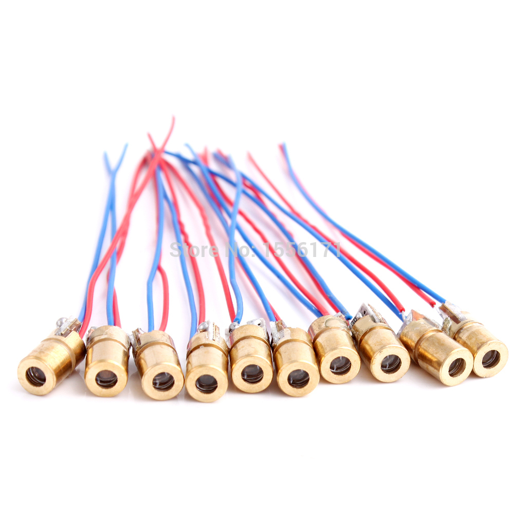
Also, finally got cheap low-powered red laser modules that I ordered a couple of weeks ago. I’m planning to use these modules throughout the design process, and then change them with more powerful green modules.
03/6/2015
Still waiting for some vital parts of my future harp, such as a MIDI jack and cable, as well as photo-diodes and resistors, to arrive. Meanwhile, decided to research non-inverting hex buffers. This decision came after reading an awesome Laser Harp Project Template written by mnsman. In this nice write-up he suggests to “add a non inverting buffer chip between all inputs and outputs of the arduino such as a cmos 4010”. I decided to find out what a CMOS 4010 is, and why it would be beneficial to the circuit. After some research I found out that CMOS 4010 is obsolete and now replaced by CMOS 4050. I also read a couple of interesting articles on Logic Gates in general and on Non-Inverting Hex Buffers in particular. However, the entire concept of a non-inverting hex buffer is still unclear to me. I understand that it has 6 buffers and none of them inverts the input (HIGH input stays HIGH, LOW stays LOW), but I absolutely don’t understand the purpose of putting this chip in the circuit, if it doesn’t change anything. Also, the wiring itself is unclear to me: should the Arduino input pins (photo-resistors) be all connected to buffers inputs, and all buffers outputs to the MIDI output? Probably, I will come back to this issue later in the process.
03/3/2015
Did some 1:1 harp enclosure parts drawings in CAD:
LH-Sample-Plate-1
LH-Sample-Plate-2
LH-Sample-Plate-3
All parts are to scale and PDFs are set up for Arch D paper (24×36). I didn’t put any dimensions on the drawings (except angular for bevels), because I’m planning to just glue the drawings directly to the lumber and cut everything out along the contour. These drawings aren’t final though. My plan is to build a sample enclosure out of pine and 1/4″ MDF or lauan first, and then modify the drawings accounting for all the drawbacks in version 1 of the enclosure. After correcting all the errors I will order some beautiful hardwood (tentatively red oak, walnut and maple panels) for the final version of the enclosure.
02/27/2015
Talked to JR about the possibility of borrowing a MIDI keyboard, and it turned out that it’s totally possible! I got a beautiful M-Audio Oxygen8 V2 keyboard and a MidiMan MidiSport 4×4 Interface.
Oxygen8 User Manual
MIDIsport 4×4 User Manual
When I first connected the MIDIsport to the laptop via USB, nothing happened and the diagnostic LED was off. At first, I thought that the interface is not working, but after reading user manual I found out that a driver is required. After some research I finally found a proper driver in M-Audio archives, installed it, and now everything works properly!
Connected the keyboard to my laptop and tested it with MuLab software. Works great!
Now, after almost all parts of my project are acquired and tested, I can start putting everything together.
02/24/2015
Downloaded and installed free MIDI software called MuLab. There are both Mac and PC versions on the web site.
02/23/2015
Found another great video – Arduino MIDI Circuit Analysis:
Also looked for MIDI keyboards on eBay – an average cost of pretty simple used keyboards is ~$70. Also, it looks like I will need a MIDI input, but almost all keyboards have only the output. If I don’t find a keyboard with MIDI IN, I will use a MIDISPORT interface (~$60 on eBay) , which we have at City Tech. I will talk to JR about a possibility of borrowing a used keyboard and probably MIDI interface from school for a couple of months until my project presentation.
02/22/2015
Did some brush up on MIDI by watching Professor Huntington’s wonderful video lecture:
Also read an article on MIDI in Wikipedia.
MIDI 5 pin connector pinout: http://www.av-tools.co.uk/pinouts/midi-5-pin
The next step will be to actually get a MIDI keyboard with MIDI IN and OUT.
02/20/2015
Did some research on NPN vs. PNP transistors. Because I have plenty of PNPs at home, I wondered wether or not it is ok to use them instead of the NPNs. After watching the following videos understood that PNPs are totally inappropriate for my project:
02/18/2015
Finally managed to send control messages to the laser. After searching on various forums found out that green laser modules are completely different in terms of control than the red ones. An NPN transistor or a FET is required to control green lasers.
Related Links:
Green Laser Control 1
Green Laser Control 2
Green Laser Control 3
After hours of trial and error got it to work:
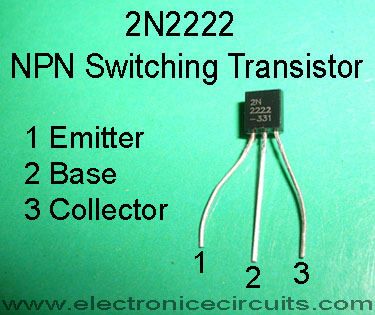
Initially I used a MOSFET transistor, but then switched to an NPN 2N2222, which is much cheaper. Below is the schematics for my setup. I couldn’t find a laser module symbol in Fritzing, so decided to use a green LED instead:
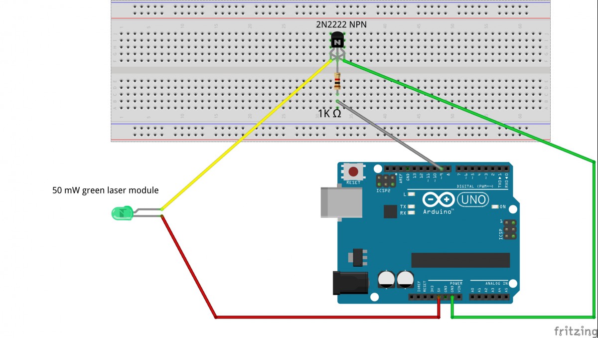
Laser’s Vcc goes to the emitter, Arduino’s digital pin 9 is connected to the base through 1K resistor, ground wire is hooked up to the collector, laser’s power goes to the 5V pin.
2N2222 Pinout:
02/16/2015
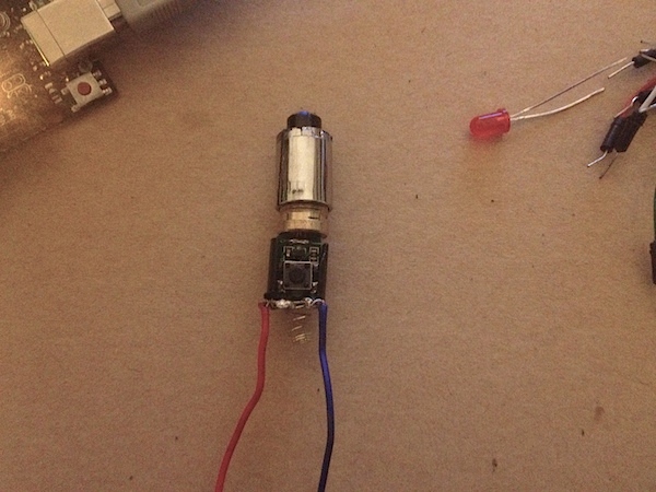
Decided to take a closer look at my non-working laser module. Noticed that I soldered the wires incorrectly, in fact creating a short circuit. Desoldered everything and soldered again, based on some pictures from the Internet. Below is a new wiring version:
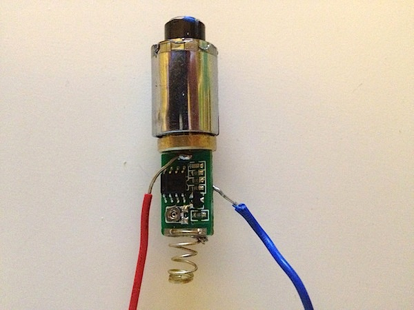
Tried it with 2 AAA batteries – it WORKS!!!
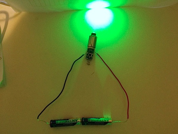
Hooked it up to the Arduino by inserting the + into pin 13 and the – into GND pin, and tried to run the Blink example – the laser does not work. However, if I insert the hot wire into 5V pin, the laser turns on:
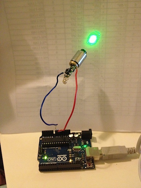
So, basically, I can power the laser module up using the Arduino as a battery, but I’m not able to control the beam.
02/14/2015
Found a useful PDF with a lot of laser modules and drivers specifications on Austrian website roithner-laser.com.
Also, found a good online tool – Resistor Finder (and many other special calculators for electronics on mustcalculate.com ).
02/13/2015
Ordered some very cheap red laser modules for prototyping purposes. My plan is to use these lasers throughout the process, and when everything (hopefully) will work, replace them with much more expensive green modules.
02/12/2015
Tested my module with two AAA batteries, and, sadly, it doesn’t work anymore. Decided to solder two wires into the driver module and test it again – doesn’t work.
 I probably damaged something while extracting the module. Now it is obvious that it would be much better to order pre-wired modules.
02/11/2015
Extracted laser module out of my 50mW laser pointer, using dremel with cutting wheel.
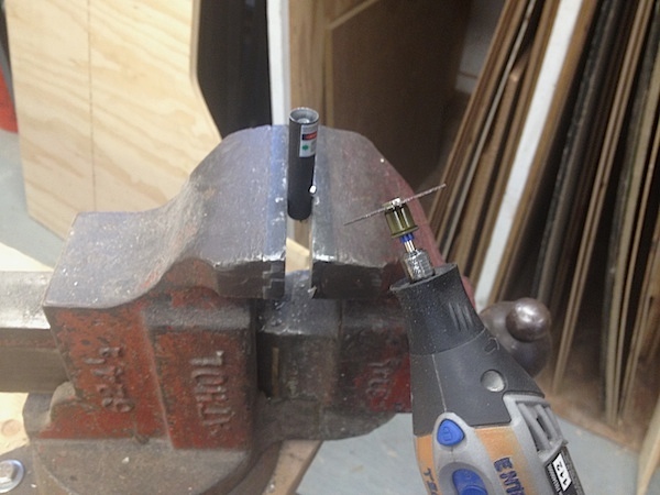
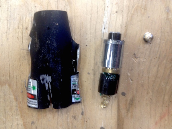
John McCullough suggested that I should just buy modules instead of extracting them from the pointers, but I decided to pull this one out anyway, just for testing purposes. If it works, I will be able to start prototyping the circuit using breadboard right away.
02/10/2015
Modified my ePortfolio according to the assignment. Created a new directory for Culmination Project course with the following subcategories: Proposal, Poster, Journal. Created a separate page for each section of Proposal. Pages are accessible through the drop down menu, and also through the Table of Contents page.
02/09/2015
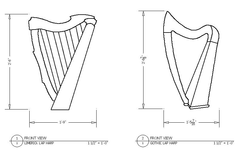
Did some initial CAD drawings of my harp. As I said before, I wasn’t able to find any affordable plans, so I decided to create my own. I used the overall dimensions provided on harp sellers websites as a guide, and simply XREFed the images of the Limerick Lap Harp and the Gothic harp that I found online into my file, scaled the pictures according to the actual dimensions, and then 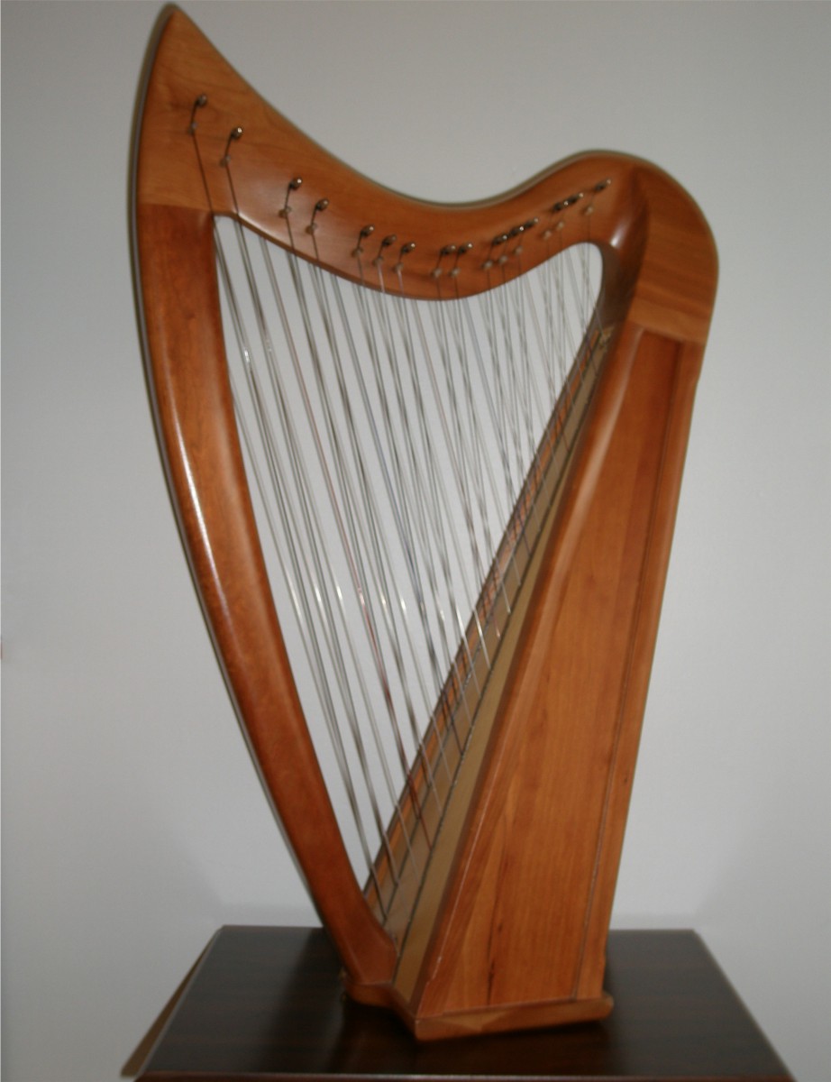 traced the outlines. Here are original pictures:
Here is what I got:
I decided to combine both views and to make the harp a little bit bigger. Here is my final drawing:
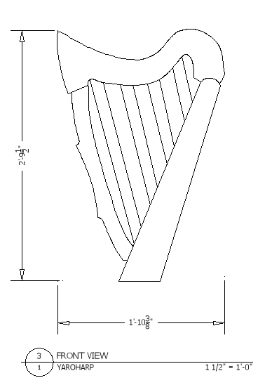 It combines the top of the Gothic harp with the bottom of the Limerick Lap Harp. My harp is a little bit higher and wider than the original harps, because I decided to use 2.5″ distance between the laser beams in order to avoid unwanted blockage of several laser beams together. Currently I only have the front view, but will also make other views and possibly assembly drawings later.
02/08/2015
Researched how to make a custom PCB (Printed Circuit Board) at home. I’m planning to use one for the interrupts for laser beams. It will be a very interesting thing to try.
There are two common methods of creating a DIY PCB:
1. Marker Method
2. Laser Printer Metod
Both methods are dealing with copper clad board and ferric chloride. I will try the second one, because it involves usage of a new software (EagleCAD), and the final product looks much more neat than the one made using the marker method.
02/07/2015
Went to Home Depot to take a look at different hardwoods for my future harp enclosure. Red oak seems to be a good choice considering cost/quality ratio. American cherry also looks great, but is more expensive than oak. Poplar is attractive and affordable, but I already worked with this material before. For my culmination I want to try something new.
 Oak is available in 1×12 sizes ($8.41/lft), so it looks like all curved parts of my harp can be laid out on the board that wide. Ideally, it would be great to use the CNC to cut out all irregular parts. I will talk to John McCullough about this possibility.
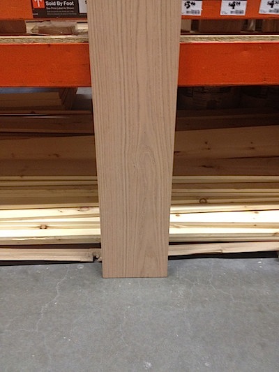
1×12 Red Oak – Nice Texture
Also, I was looking for purpleheart and walnut appearance boards, but unfortunately Home Depot doesn’t have any. I looked online, and was not happy about pricing. However, I found out that lumberyards have different notations for hardwood lumber sizes, which was very useful. Hardwoods come in 4/4, 5/4, 6/4, 8/4 etc. sizes, as opposed to regular 1×4, 1×6 etc. Here is a good explanation of the numbering system.
I decided not to buy anything until I know for sure the quantity and the type of wood I need. I will build a prototype out of pine first, and then spend money on expensive lumber.
02/06/2015
Did some research on regular harps, and found out that there are two big groups of these instruments: Pedal Harps (also known as Concert or Classical) and Lever (Non-Pedal) Harps. Here is a good article on their differences. Also, found a nice write-up on Kinds and History of Harps. After some thinking, I chose to replicate a Celtic Lap Harp (lever), but my harp won’t be used as a regular instrument, so lap placement is not necessary. Instead, my harp will be a free standing device.
Next, I decided to look for specific models and possibly plans. Almost all plans that I found were either quite expensive or made for big pedal harps. After some more research I finally found something that I liked: Limerick Lap Harp. It could be even bought as kit (although extremely expensive) and assembled. On the same web site there was a very helpful PDF file with Assembly Instructions, from which I got a general idea on how different parts of this harp go together.
02/04/2015
Had the first meeting with Professor Baker, who will be my faculty advisor. During the meeting we discussed the concept, outlined further research directions, and tested two green laser pointers that I brought with me. One of them was “<50mW” (which is 10 times greater than regular laser pointers) and costed ~$15. Another one was “<100mW”, had focus feature, key lock, and special battery with charger (~$45).
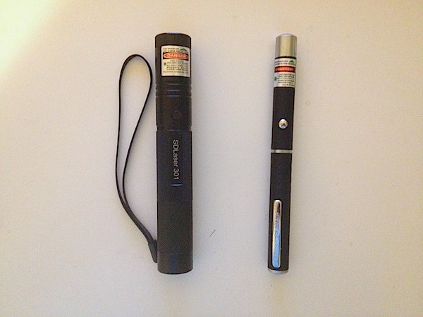
Although the second laser was brighter than the first one, we decided to use 50mW lasers in order to cut expenses.
Professor Baker suggested that I should research real harps’ shapes and dimensions and replicate one of them in my design. He also said that it will be much better to use photo diodes instead of photo resistors. As for lasers placement and orientation, he suggested to place the modules on the upper part of laser harp pointing downwards in order to avoid accidental beam/eye contact.
02/03/15
Met with Professor Huntington, who suggested that either Professor Patton or Professor Baker should be my faculty advisor.
Researched some laser operation related policies, such as:
Laser Training
ILDA Certification Programs
NY Department of Labor Code 61 Subpart 61-5 Special Provisions for Mobile Laser Operators
Mobile Laser Operator Certificate Application Forms
When reading the Code 61, I found out that certification is not required if “lasers are used exclusively in research and development” (Section 61 – 5.1(d) Application)
02/02/15
Researched framed and frameless Laser Harps on the following hobbyists’ and professional web sites:
CiboMahto.com
Humboldt Microcontrollers Comunity
AndrewKilpatrick.org
Arduino
open-source-energy.org
Harp Laser Blog
Harpelaser.com
StephenHobley.com
Instructables
Makezine
Decided that I definitely want to make a framed (not frameless) harp.
01/30/15
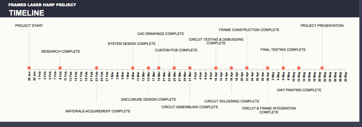
Readjusted the structure of the Project Proposal document that I already had in accordance with the new assignment. Created Project Timeline document in Microsoft Excel.

