Randal Umpierre
7-5-13
Project Concept
For my summer internship project, I choose to work on an electric motor driven bicycle with ERT (Energy Recovery Technology). I choose to work on this project because of the timetable allotted to me, my familiarity with bicycles, and because of the potential practicality that this bicycle will bring to cyclists. The concept that I have in mind will not eliminate pedaling, however it will allow cyclists to achieve a higher top speed, acceleration time, and reuse recycled kinetic energy. The bicycle would use three motors. One to power the rear wheel, another to power the front wheel, and a third motor fully integrated into the crankshaft. The power from the crankshaft motor would power the other motors located on the rear and front wheels. The flywheels would be located on the right sides of the front and rear wheels. They would be attached through direct integration and would spin in the forward direction through the use of one way bearings. The frame design would be a smaller design that is lower to the ground and would have a suspension system for better handling.

Figure 1: Concept of the bike with ERS (Design 1)

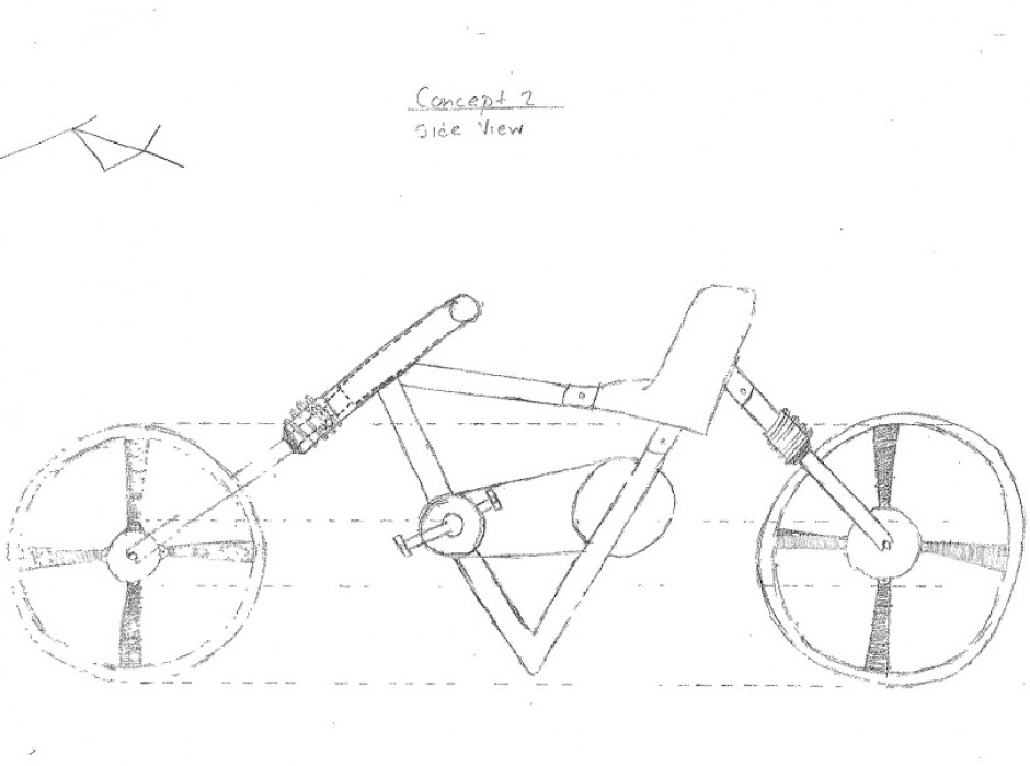
Figure 2: Concept of the bike with ERS (Design 2)

Figure 2A: Design discussion
—————-
Home > Project Overview


Could you explain Design 1 & 2, including dimensions etc?
Randal,
You did a good job for starting brainstorming for the design.
Regarding Fig 2, I have several questions:
1) Why you put the triangle frame connecting the seat, handle, and pedal?
2) Where is the suspensions?
3) Where is the ERS unit?
Please put a reply under this post.
Regards,
MRN
Answer to question 1 – I did this because this because triangular shapes are very strong and aren’t too complicated. It firmly secures and integrates the seat and the crankshaft into the frame of the bike.
Answer to question 2 – The shock absorbers are on the front and rear legs of the bike frame.
Answer 3 – On the first design, there are two flywheels, and they are on the front and rear wheels of the bicycle. On the second design, there is one flywheel, and it is driven by the crankshaft and is wedged between the the center of the frame beam that connects to the bottom of the seat.
I understand that the absorbers are at blue circles and a flywheel is at a green circle in Fig 2A.
Since absorbers are located at blue circles and the angle of the triangle is a same level of tires, the angle will hit the ground.
4) Why the angle should be near the ground, which doesn’t make sense as an engineering design?
5) Why is the flywheel so small in Figure 2? How much energy do you think the flywheel can store, comparing with the design in Figure 1?
Answer to question 4 – You’re right. I’ll modify the frame of the concepts so there will be enough clearance between the ground and the bottom of the frames.
Answer to question 5 – The flywheel has to be small to fit into the center of the frame without interfering with the driver or the other components. If the wheel is of sufficient density, tensile strength, and size, it should collect a reasonable amount of energy.
Please calculate how much energy you can store such a small flywheel. I showed the equations and discuss the calculation is important. The flywheel in the center of the frame like the Cooper Union’s project is a great idea. However you cannot just copy the design from them.