LESSON 3: Introduction to Architectural Drawings: Elevations
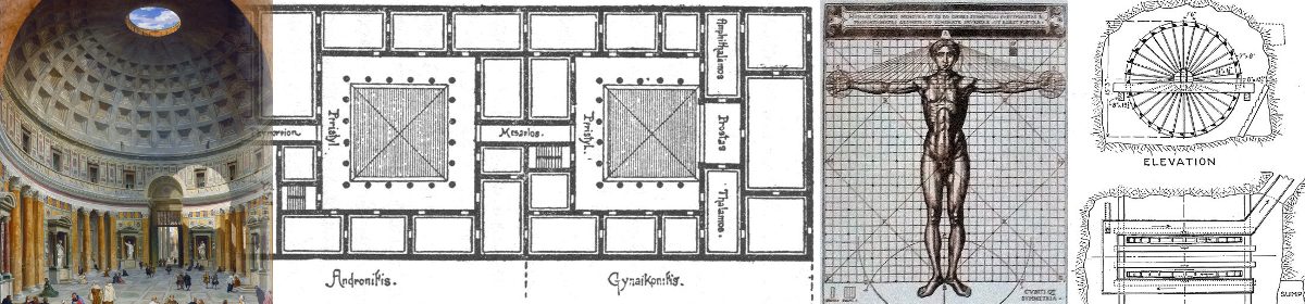
Students investigate the correspondence between the elevation of a building, which they see, and the plan and section of the building, which they don’t. Examples from history will illustrate the interrelationship between plan, section, and elevation.
Students work from a dimensioned sketch of a small building to draft its four elevations. They continue to develop drawing methods used in the typical architectural practice. Students review and practice the use of drafting strategies introduced in ARCH 1112 that will further be developed in ARCH 1122 and apply these methods to a more complex drawing problem. Concepts covered will include review of orthographic projection drawings, familiarity with architectural graphic standards and notations such as lettering and dimensioning.
Elevation
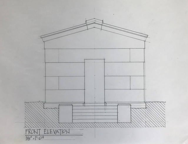
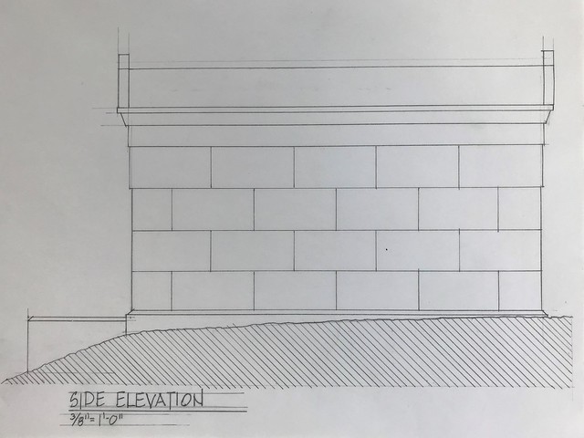
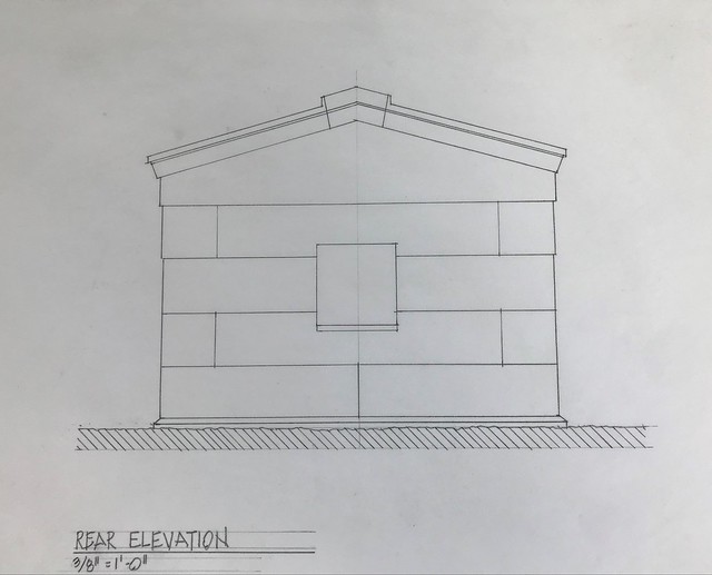
An elevation is a representation of a vertical surface of a building, either a facade of the exterior or a wall in the interior. In an elevation the architect represents the fenestration of the exterior or in the interior, the windows, doors, and other architectural elements apparent to the eye.
When drawn correctly, the plans, sections, and elevations of a building all correspond to each other. (E.g. the window represented in the elevations will also appear in the plans as horizontal cuts in the exterior wall, and in the sections as vertical cuts.)
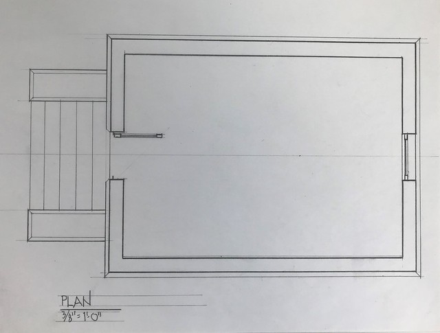
Plan
A plan is a horizontal cut through a building usually taken about three to four feet above the floor. At this height, the architect can show the relationships of the walls, doors, windows, and other elements of the building. The plan is the primary representation the architect uses to convey the relationship of the program components of the building.
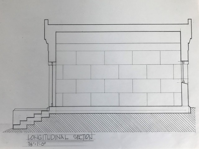
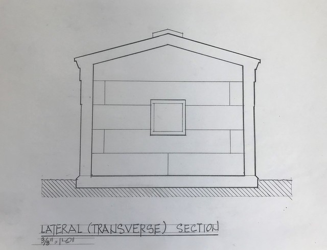
Section
A section is a vertical cut through the building. It can be taken in multiple positions and in multiple directions. Usually the architect selects a position that will reveal most about the vertical relationships in the building: through a stair, for example, or through a multi-story space. Sections are often drawn so that they are orthogonal to each other. A section from the front to the back of a building is called a longitudinal section, and one that is cut from side to side is called a lateral or transverse section.
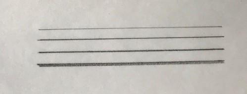
Line Weights
In order to represent distance in a flat orthogonal drawing, architects will vary the thickness of the lines: a thicker line appears darker and closer to the viewer; a thin line appears light and farther away. We call this variation in the line weight. It is important to remember that all the lines are the same darkness, it’s just that their thicknesses vary. (In other words, don’t bear down on the lead to make the line darker; you’ll break the lead, tear the paper, or both.)
Construction lines
When drafting a plan, section, or elevation it is often helpful to lightly block out the building to confirm the relationships, proportions, and dimensions. You can then go over your construction lines and adjust the line weights to make the drawing easier to read. If some of the original construction lines remain, it’s okay; it actually can enhance the beauty of the drawing. Some architects will overlay the block out with another piece of tracing paper and trace over the underlay with the proper line weights. This way no construction lines appear in the final drawing.
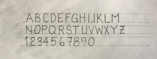
Lettering
Writing text on drawings is necessary to note what the drawing is showing. The letters on the drawings are ALWAYS upper case (capital) letters. For a typical note, architects will draw horizontal guidelines about 1/8” apart and carefully fit the letters between the lines. Titles may be larger 1/4”, 1/2″.
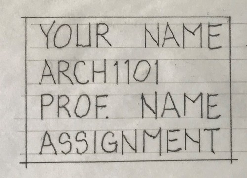
Title Block
All drawings will have a title block with the following information:
Class Schedule
Quiz: From the assigned reading. You may use your notes.
Demonstration: lettering and line weights
Exercise: Draw the top view (plan) of the object below, then draw the four elevations as shown in the diagram below. Using a 12” x 18” piece of trace paper, choose a scale that will fit all five drawings. Use your parallel rule to align the sheet before you tape it down.
Lab: Using the dimensioned sketches of a pavilion from Greenwood Cemetery that has been measured by the professor, draft on 12×18 piece of white tracing paper each of the four elevations at ½”=1’-0”. Attention will be given to line consistency and line weights.
PLEASE NOTE: ALL DRAFTING ASSIGNMENTS WILL BE DONE ON 12”X18” WHIITE TRACING PAPER. A DRAWING ASSIGNMENT IN ANY OTHER FORMAT WILL NOT BE GRADED!
Assignment
See Assignments in menu bar

