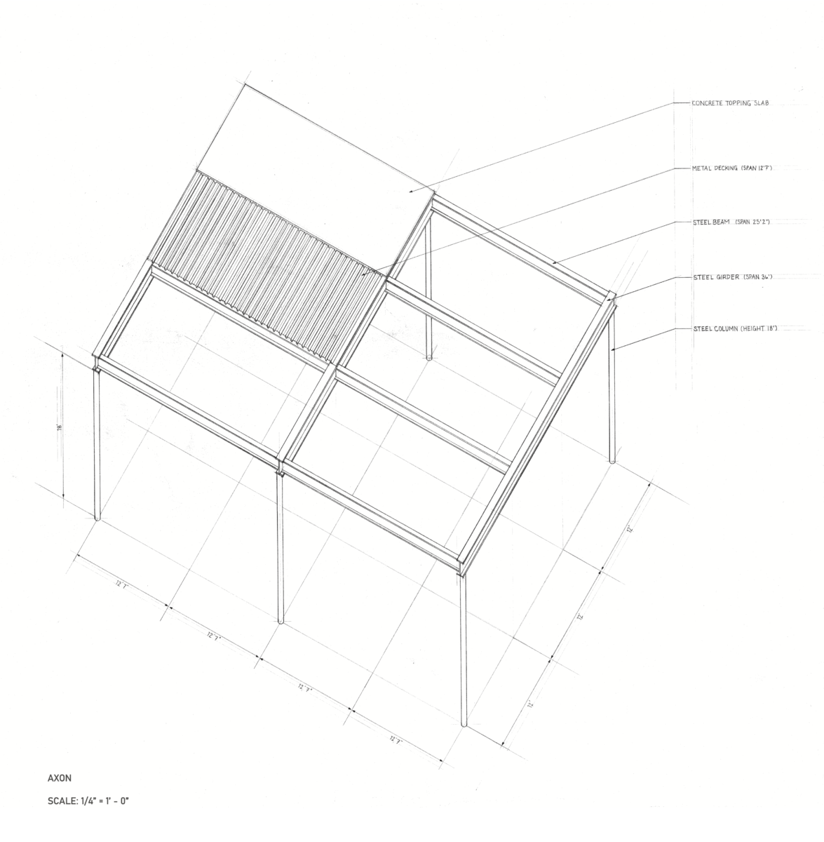
This assignment combines the development of a three dimensional representation of the selected structural bays of the case study building and the application of a structural system to span between columns, to create a floor deck above. Each structural element will be sized using simple rules of thumb. The full system will be documented as an axon and component section views of each element of the system. All elements are to be dimensioned, labeled, and annotated with details including the span dimension and the rule of thumb applied as well as the reference for the rule of thumb. Below is a sample axonometric drawing.
Learning Outcomes
| Learning Outcomes | Assessment Methods |
| Upon successful completion of this assignment the student shall be able to: | To evaluate the students’ achievement of the learning objectives, the professor will do the following: |
| Develop coordinated, accurate, and consistent axonometric views demonstrating the proper use of axon drawing conventions. | Review student case study floor plans for accuracy, coordination, and consistency as well as the application of line weight and drawing conventions following assignment rubric. |
| Apply Information from the reading within the discipline. | Review student applications of disciplinary concepts in drawing assignments. |
| Understand and apply basic principles of structural characteristics of materials following rules of thumb. | Review student drawing assignments for accurate application of rules of thumb to sizing structural elements for a specific span. |
Assignment Context:
This assignment is focused on applying the reading material (mostly Readings 9 and 10) to help build a deeper understanding and direct experience of the concepts discussed in the text.
Prerequisites:
Understanding of three-dimensional projection, completion of the required readings.
Recommended Text:
Ching, Francis. Architecture Graphics. John Wiley and Sons, 2009.
Plagiarism:
Student work submitted must be original and developed individually. Tracing is not acceptable. All construction lines and notations during drawing construction are to remain visible at final submission. Drawings without construction lines (guidelines) will be downgrading significantly.
Instructions
NOTE: Both drawings to be on 12″x 18″ sheets at scale listed below unless otherwise agreed with your Professor.
Final Deliverables:
- Page 1 – Structural Bay Axonometric @ 1/8″ = 1′-0″
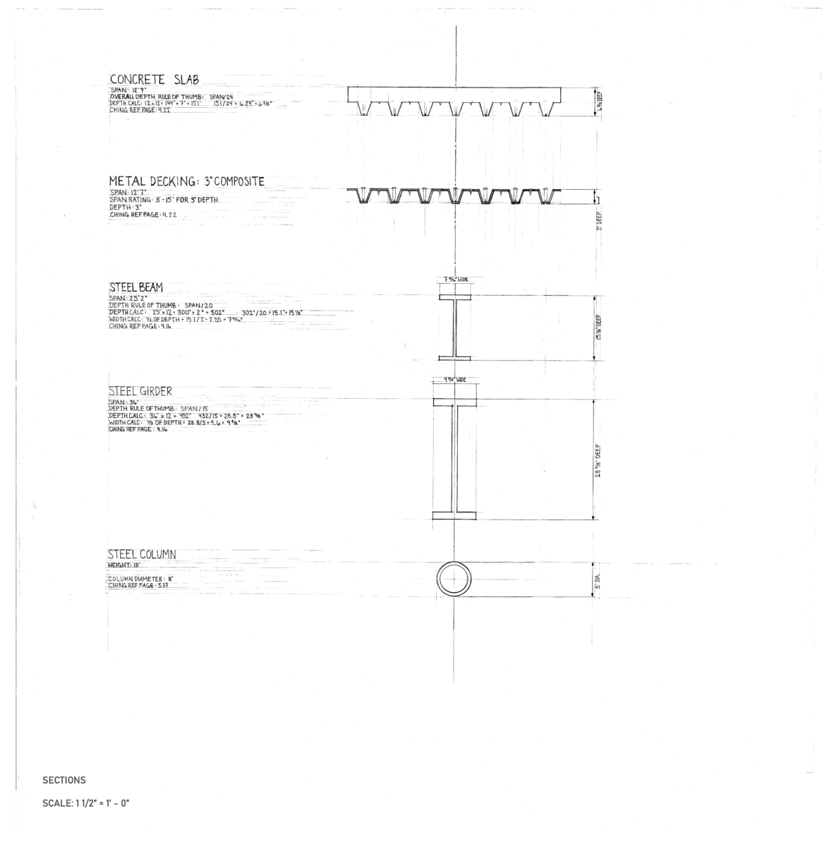
- Page 2 – Structural Component Sections @ 1-1/2″=1′-0″ each with Calculations, references, and full Annotations, Labeled and dimensioned (Lettering to be 1/8″ high )
Follow these steps:
- Draw a Centerline vertically on your sheet. Centered on this line, Sketch each Structural Component: Column, Girder, Beam, Metal Deck, Wire Mesh, and Concrete.
- Start with the Column at the bottom of the page. Rough out an approximate width and height of each Component. Then work through the calculations using rules of thumb for each component. Show the mathematics and calculations, translate all dimensions to inches and show all work.
- Refine your Component Sketch to reflect the dimensions you calculated and draw any added details. For example, the Girder may end up being 29 5/8″ in height, have a specific radius where the web meets the flange, have a thinner web and squared edges. Label each part in section and dimension depth and width and other calcs.
- Layout out reference lines for axon detail (structural grid lines and primary guide lines)
- Using guidelines, indicate vertical structural elements (18′ tall, square or round in section)
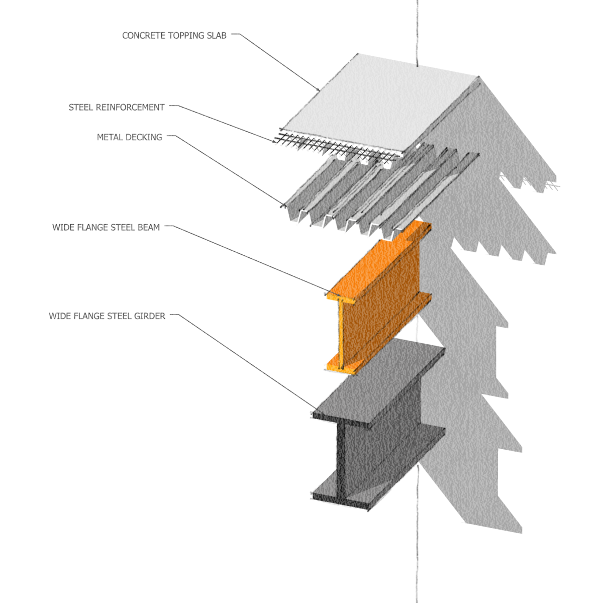
- Working in the sequence of construction, layout each layer of elements using peel away strategy to show clearly each layer (see mockup above)
- Finally axon line weights and annotate each component in system.
- On second sheet, draw center line for component sections
- Using guidelines, layout each component section at required scale, started with the primary beams 1″ above the bottom of the sheet.
- Add dimension strings to each component to indicate depth and width. See guide for dimensions here and for lettering here
- Using 1/8″ lettering, with space between each line, show all steps of structural calculations, including page reference for Ching’s rules of thumb.
- Complete each of these drawings. Scan on flatbed scanner and format per the course formatting guidelines (found here)
- Submit all formatted files as directed by your professor.


Leave a Reply